
Arduino Mega 2560-Based Smart Vehicle Safety System with GPS and GSM
View and Edit Project In Cirkit Designer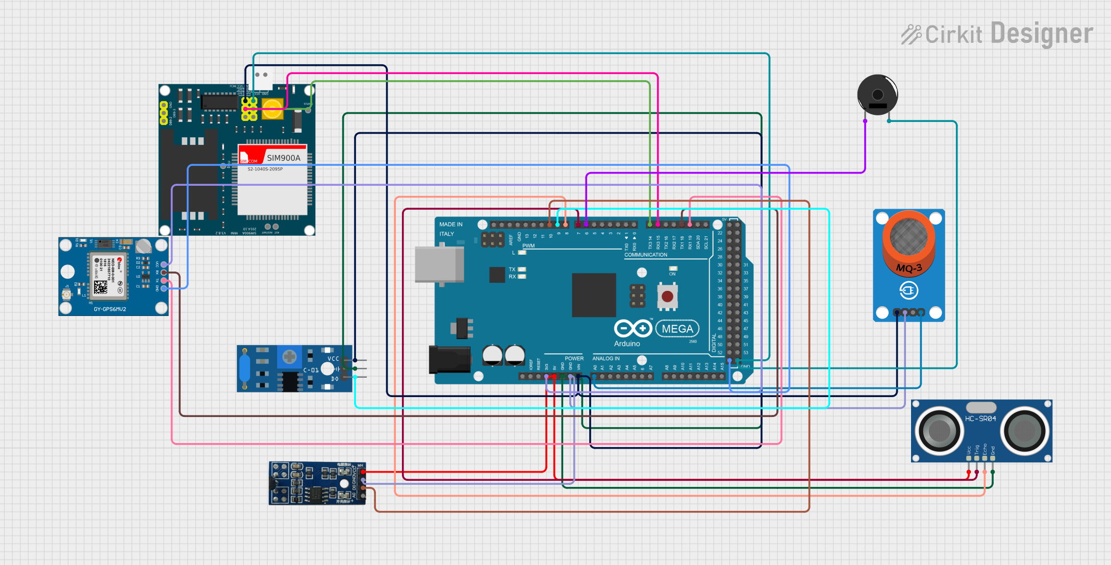
Circuit Documentation
Summary
This document provides a detailed overview of a circuit designed using an Arduino Mega 2560 microcontroller. The circuit integrates various sensors and modules, including a SIM900A GSM module, a Neo 6M GPS module, an HC-SR04 ultrasonic sensor, an SW-420 vibration sensor, a Hall sensor, an MQ-3 alcohol sensor, and a piezo buzzer. The system is designed to monitor alcohol levels, detect vibrations, measure speed, and ensure the use of a helmet or seatbelt. It also includes functionalities for sending SMS alerts and making missed calls in case of emergencies.
Component List
Arduino Mega 2560
- Description: Microcontroller board based on the ATmega2560.
- Pins: IOREF, RESET, 3V3, 5V, GND, VIN, A0-A15, D0-D53, PWM, AREF, SDA, SCL.
SIM900A
- Description: GSM/GPRS module for communication.
- Pins: GND, DB9-3 (RXD), DB9-2 (TXD), 5V, 3VR, 5VR, 3VT, 5VT, VCC, Ring, RESTART, RESET, STATUS.
Neo 6M GPS Module
- Description: GPS module for location tracking.
- Pins: GND, TX, RX, VCC.
Piezo Buzzer
- Description: Buzzer for audio alerts.
- Pins: pin 1, pin 2.
HC-SR04 Ultrasonic Sensor
- Description: Ultrasonic sensor for distance measurement.
- Pins: VCC, TRIG, ECHO, GND.
SW-420 Vibration Sensor
- Description: Vibration sensor for detecting vibrations.
- Pins: vcc, Ground, Digital output.
Hall Sensor (Magnetic)
- Description: Magnetic sensor for detecting magnetic fields.
- Pins: VCC (5V), GND, D0 (Digital), A0 (Analog).
MQ-3 Breakout
- Description: Alcohol sensor for detecting alcohol levels.
- Pins: VCC, GND, DO, AO.
Wiring Details
Arduino Mega 2560
- 3V3 connected to VCC of Neo 6M GPS Module.
- 5V connected to VCC of HC-SR04 Ultrasonic Sensor and VCC (5V) of Hall Sensor.
- VIN connected to VCC of SIM900A, VCC of MQ-3 Breakout, and vcc of SW-420 Vibration Sensor.
- GND connected to GND of HC-SR04 Ultrasonic Sensor, Ground of SW-420 Vibration Sensor, GND of MQ-3 Breakout, GND of Hall Sensor, GND of Neo 6M GPS Module, GND of SIM900A, and pin 2 of Piezo Buzzer.
- A0 connected to AO of MQ-3 Breakout.
- D19/RX1 connected to TX of Neo 6M GPS Module.
- D18/TX1 connected to RX of Neo 6M GPS Module.
- D15/RX3 connected to 5VT of SIM900A.
- D14/TX3 connected to 5VR of SIM900A.
- D6 PWM connected to pin 1 of Piezo Buzzer.
- D7 PWM connected to TRIG of HC-SR04 Ultrasonic Sensor.
- D8 PWM connected to ECHO of HC-SR04 Ultrasonic Sensor.
- D9 PWM connected to Digital output of SW-420 Vibration Sensor.
- D10 PWM connected to D0 (Digital) of Hall Sensor.
SIM900A
- VCC connected to VIN of Arduino Mega 2560.
- 5VT connected to D15/RX3 of Arduino Mega 2560.
- 5VR connected to D14/TX3 of Arduino Mega 2560.
- GND connected to GND of Arduino Mega 2560.
Neo 6M GPS Module
- VCC connected to 3V3 of Arduino Mega 2560.
- TX connected to D19/RX1 of Arduino Mega 2560.
- RX connected to D18/TX1 of Arduino Mega 2560.
- GND connected to GND of Arduino Mega 2560.
Piezo Buzzer
- pin 1 connected to D6 PWM of Arduino Mega 2560.
- pin 2 connected to GND of Arduino Mega 2560.
HC-SR04 Ultrasonic Sensor
- VCC connected to 5V of Arduino Mega 2560.
- TRIG connected to D7 PWM of Arduino Mega 2560.
- ECHO connected to D8 PWM of Arduino Mega 2560.
- GND connected to GND of Arduino Mega 2560.
SW-420 Vibration Sensor
- vcc connected to VIN of Arduino Mega 2560.
- Ground connected to GND of Arduino Mega 2560.
- Digital output connected to D9 PWM of Arduino Mega 2560.
Hall Sensor (Magnetic)
- VCC (5V) connected to 5V of Arduino Mega 2560.
- GND connected to GND of Arduino Mega 2560.
- D0 (Digital) connected to D10 PWM of Arduino Mega 2560.
MQ-3 Breakout
- VCC connected to VIN of Arduino Mega 2560.
- GND connected to GND of Arduino Mega 2560.
- AO connected to A0 of Arduino Mega 2560.
Code Documentation
#include <SoftwareSerial.h>
#include <Wire.h>
#include <Adafruit_GPS.h>

// Pin definitions
#define ALCOHOL_SENSOR_PIN A0
#define ULTRASONIC_TRIG_PIN 7
#define ULTRASONIC_ECHO_PIN 8
#define MOTOR_PIN 5
#define SPEED_SENSOR_PIN 10
#define VIBRATION_SENSOR_PIN 9
#define BUZZER_PIN 6
#define BUTTON_PIN 12

// GSM and GPS pins
SoftwareSerial gpsSerial(19, 18);  // RX, TX for GPS
SoftwareSerial gsmSerial(15, 14);  // RX, TX for GSM

Adafruit_GPS GPS(&gpsSerial);

// Variables
bool alcoholDetected = false;
bool helmetSeatbeltDetected = false;
bool engineStarted = false;
bool overSpeed = false;
bool vibrationDetected = false;
int speedLimit = 80;  // Speed limit in km/h

// Function to read alcohol level
bool readAlcoholSensor() {
  int sensorValue = analogRead(ALCOHOL_SENSOR_PIN);
  if (sensorValue > 200) {  // Adjust threshold based on calibration
    return true;  // Alcohol detected
  }
  return false;  // No alcohol detected
}

// Function to check seatbelt/helmet (ultrasonic distance)
bool checkHelmetSeatbelt() {
  long duration, distance;
  digitalWrite(ULTRASONIC_TRIG_PIN, LOW);
  delayMicroseconds(2);
  digitalWrite(ULTRASONIC_TRIG_PIN, HIGH);
  delayMicroseconds(10);
  digitalWrite(ULTRASONIC_TRIG_PIN, LOW);
  duration = pulseIn(ULTRASONIC_ECHO_PIN, HIGH);
  distance = duration * 0.0344 / 2;  // Calculate distance in cm

  if (distance < 30) {  // If hand is close to the sensor, assume helmet/seatbelt is on
    return true;
  }
  return false;
}

// Function to read speed sensor
int readSpeedSensor() {
  static unsigned long lastTime = 0;
  static int pulseCount = 0;
  unsigned long currentTime = millis();
  if (digitalRead(SPEED_SENSOR_PIN) == HIGH) {
    pulseCount++;
  }

  if (currentTime - lastTime > 1000) {  // Update speed every second
    lastTime = currentTime;
    int speed = pulseCount * 60 / 2;  // Adjust according to the sensor setup
    pulseCount = 0;
    return speed;
  }
  return 0;
}

// Function to send SMS
void sendSMS(String message) {
  gsmSerial.println("AT+CMGF=1");  // Set SMS mode
  delay(100);
  gsmSerial.println("AT+CMGS=\"+919641646315\"");  // Send SMS to the specified number
  delay(100);
  gsmSerial.println(message);  // Send message
  delay(100);
  gsmSerial.write(26);