
Arduino Mega 2560-Based Autonomous Robot with IR Sensors and 3D LIDAR
View and Edit Project In Cirkit Designer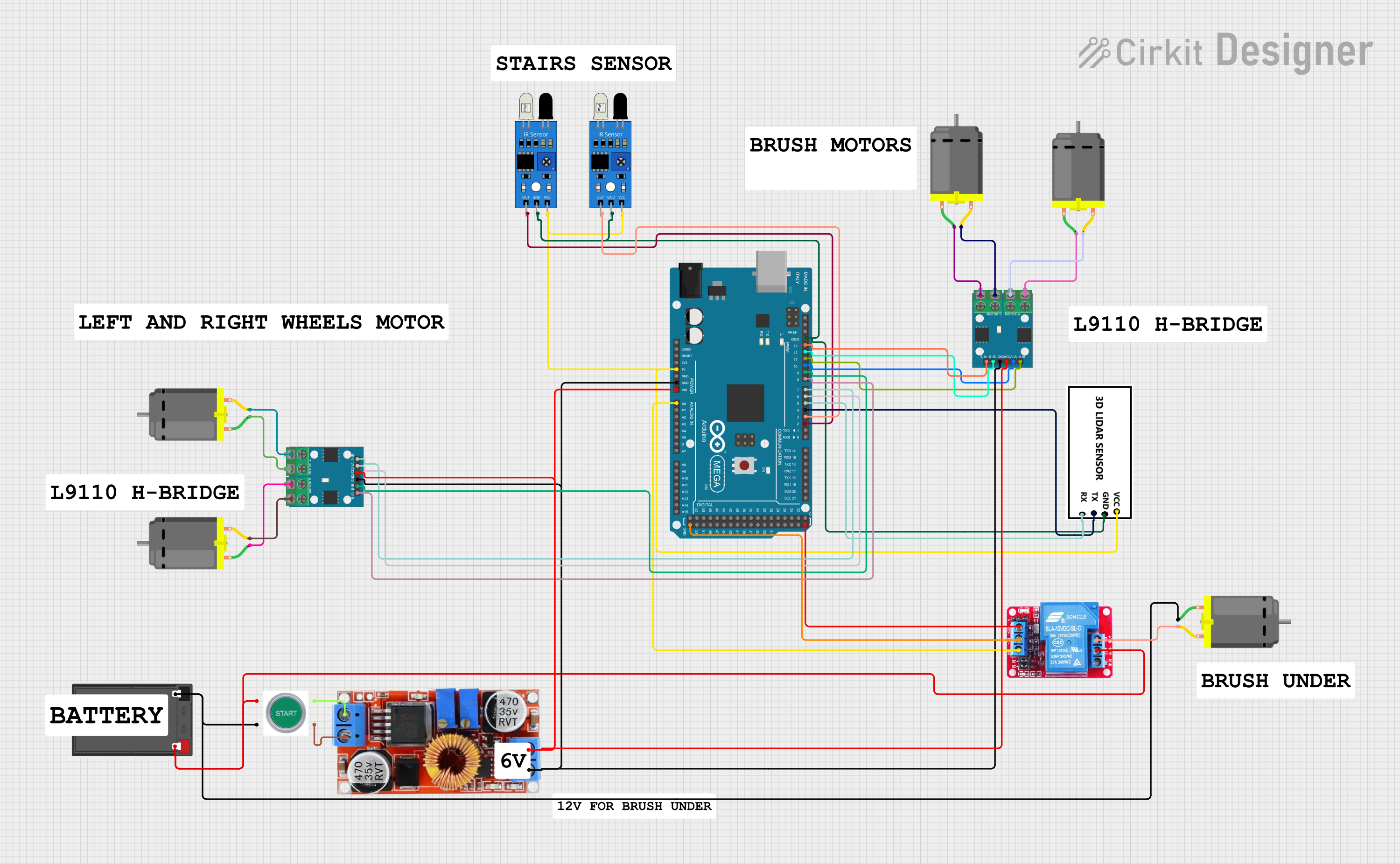
Circuit Documentation
Summary
This document provides a detailed overview of a circuit that includes various sensors, motors, a microcontroller, and other components. The circuit is designed to interface with an Arduino Mega 2560, which controls the operation of the connected components. The components include IR sensors, DC motors, a 3D LIDAR, a relay, a step-down regulator, and a start switch. The document includes a component list, wiring details, and the embedded code used in the microcontroller.
Component List
IR Sensor
- Description: Infrared sensor used for detecting objects.
- Pins: out, gnd, vcc
DC Motor
- Description: Direct Current motor used for mechanical movement.
- Pins: pin 1, pin 2
3D LIDAR
- Description: Light Detection and Ranging sensor used for distance measurement.
- Pins: VCC, GND, TX, RX
Battery
- Description: Power source for the circuit.
- Pins: -, +
Arduino Mega 2560
- Description: Microcontroller used to control the circuit.
- Pins: IOREF, RESET, 3V3, 5V, GND, VIN, A0-A15, D0-D53, AREF, SDA, SCL
Start Switch
- Description: Switch used to start the circuit.
- Pins: NO 1, NC 1, NO 2, NC 2
L9110
- Description: Motor driver used to control the DC motors.
- Pins: MOTOR B-A, MOTOR B-B, MOTOR A-A, MOTOR A-B, B-IA, B-IB, GND, VCC, A-IA, A-IB
12V Relay
- Description: Relay used to control high voltage components.
- Pins: NO, COM, NC, DC+, DC-, IN
Regulator Stepdown DC XL4015 CC CV
- Description: Step-down voltage regulator.
- Pins: IN +, IN -, OUT +, OUT -
Wiring Details
IR Sensor
- vcc connected to 5V of Arduino Mega 2560
- gnd connected to GND of Arduino Mega 2560
- out connected to D2 PWM of Arduino Mega 2560 (for one sensor)
- out connected to D3 PWM of Arduino Mega 2560 (for the other sensor)
DC Motor
pin 1 connected to MOTOR A-B of L9110
pin 2 connected to MOTOR A-A of L9110
pin 1 connected to MOTOR B-A of L9110
pin 2 connected to MOTOR B-B of L9110
pin 1 connected to MOTOR A-A of another L9110
pin 2 connected to MOTOR A-B of another L9110
pin 1 connected to MOTOR B-B of another L9110
pin 2 connected to MOTOR B-A of another L9110
3D LIDAR
- VCC connected to 5V of Arduino Mega 2560
- GND connected to GND of Arduino Mega 2560
- TX connected to D4 PWM of Arduino Mega 2560
- RX connected to D5 PWM of Arduino Mega 2560
Battery
- - connected to NC 1 of Start Switch
- + connected to NO 1 of Start Switch
Arduino Mega 2560
- 5V connected to vcc of IR sensors and VCC of 3D LIDAR
- GND connected to gnd of IR sensors and GND of 3D LIDAR
- VIN connected to OUT + of Regulator Stepdown DC XL4015 CC CV
- A0 connected to IN of 12V Relay
- D2 PWM connected to out of one IR sensor
- D3 PWM connected to out of the other IR sensor
- D4 PWM connected to TX of 3D LIDAR
- D5 PWM connected to RX of 3D LIDAR
- D6 PWM connected to A-IA of L9110
- D7 PWM connected to A-IB of L9110
- D8 PWM connected to B-IA of L9110
- D9 PWM connected to B-IB of L9110
- D10 PWM connected to A-IA of another L9110
- D11 PWM connected to A-IB of another L9110
- D12 PWM connected to B-IB of another L9110
- D13 PWM connected to B-IA of another L9110
Start Switch
- NO 1 connected to + of Battery
- NC 1 connected to - of Battery
- NO 2 connected to IN + of Regulator Stepdown DC XL4015 CC CV
- NC 2 connected to IN - of Regulator Stepdown DC XL4015 CC CV
L9110
GND connected to GND of Arduino Mega 2560
VCC connected to OUT + of Regulator Stepdown DC XL4015 CC CV
A-IA connected to D6 PWM of Arduino Mega 2560
A-IB connected to D7 PWM of Arduino Mega 2560
B-IA connected to D8 PWM of Arduino Mega 2560
B-IB connected to D9 PWM of Arduino Mega 2560
GND connected to GND of Arduino Mega 2560
VCC connected to OUT + of Regulator Stepdown DC XL4015 CC CV
A-IA connected to D10 PWM of Arduino Mega 2560
A-IB connected to D11 PWM of Arduino Mega 2560
B-IA connected to D13 PWM of Arduino Mega 2560
B-IB connected to D12 PWM of Arduino Mega 2560
12V Relay
- IN connected to A0 of Arduino Mega 2560
- DC+ connected to 5V of Arduino Mega 2560
- DC- connected to GND of Arduino Mega 2560
- COM connected to NO 1 of Start Switch
- NO connected to pin 2 of a DC Motor
Regulator Stepdown DC XL4015 CC CV
- IN + connected to NO 2 of Start Switch
- IN - connected to NC 2 of Start Switch
- OUT + connected to VIN of Arduino Mega 2560 and VCC of L9110
- OUT - connected to GND of Arduino Mega 2560 and GND of L9110
Documented Code
Arduino Mega 2560 Code
void setup() {
  // put your setup code here, to run once:

}

void loop() {
  // put your main code here, to run repeatedly:

}
This code is a basic template for the Arduino Mega 2560. The setup function is used to initialize any settings or configurations, and the loop function contains the main code that runs repeatedly.