Arduino Nano-Based Wireless Motion Detection System with LED Indicator
Circuit Documentation
Summary
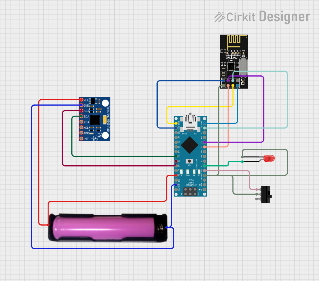
This document provides a detailed overview of a circuit that includes an Arduino Nano as the central microcontroller, interfaced with an NRF24L01 wireless transceiver module, an MPU-6050 accelerometer/gyroscope, an 18650 battery in a holder for power supply, a red two-pin LED, and a toggle switch. The Arduino Nano is programmed to control and interact with these components, although the specific functionalities are not defined in the provided code.
Component List
Arduino Nano
- Microcontroller board based on the ATmega328P
- It has a variety of digital and analog I/O pins.
NRF24L01
- A wireless transceiver module that operates in the 2.4 GHz band.
- It communicates with the microcontroller via SPI.
MPU-6050
- A motion-tracking device that contains a 3-axis accelerometer and a 3-axis gyroscope.
- It communicates with the microcontroller via I2C.
18650 Battery in Holder
- A rechargeable lithium-ion battery that provides power to the circuit.
- It is commonly used for its high energy density and long life.
LED: Two Pin (red)
- A simple red light-emitting diode that can be used as an indicator light.
- It has an anode and a cathode for connection.
Toggle Switch
- A switch that can connect or disconnect the circuit, controlling the power or signal flow.
- It has three terminals: one common (COM) and two for switching (L1, L2).
Wiring Details
Arduino Nano
- GND: Connected to the ground plane of the circuit.
- D2: Connected to the toggle switch (L1).
- D3: Connected to the anode of the red LED.
- D7: Connected to the CE pin of the NRF24L01.
- D8: Connected to the CSN pin of the NRF24L01.
- D11/MOSI: Connected to the MOSI pin of the NRF24L01.
- D12/MISO: Connected to the MISO pin of the NRF24L01.
- D13/SCK: Connected to the SCK pin of the NRF24L01.
- 5V: Connected to the VCC of the 18650 battery holder and VCC of the MPU-6050.
- 3V3: Connected to the VCC (3V) of the NRF24L01.
- A4: Connected to the SDA pin of the MPU-6050.
- A5: Connected to the SCL pin of the MPU-6050.
NRF24L01
- GND: Connected to the ground plane of the circuit.
- CE: Connected to D7 of the Arduino Nano.
- CSN: Connected to D8 of the Arduino Nano.
- MOSI: Connected to D11/MOSI of the Arduino Nano.
- MISO: Connected to D12/MISO of the Arduino Nano.
- SCK: Connected to D13/SCK of the Arduino Nano.
- VCC (3V): Connected to the 3V3 output of the Arduino Nano.
MPU-6050
- VCC: Connected to the 5V output of the Arduino Nano.
- GND: Connected to the ground plane of the circuit.
- SCL: Connected to A5 of the Arduino Nano.
- SDA: Connected to A4 of the Arduino Nano.
18650 Battery in Holder
- VCC: Connected to the 5V input of the Arduino Nano and VCC of the MPU-6050.
- GND: Connected to the ground plane of the circuit.
LED: Two Pin (red)
- Anode: Connected to D3 of the Arduino Nano.
- Cathode: Connected to the ground plane of the circuit through the toggle switch (COM).
Toggle Switch
- COM: Connected to the ground plane of the circuit.
- L1: Connected to D2 of the Arduino Nano.
Documented Code
Arduino Nano Code (sketch.ino)
void setup() {
  // put your setup code here, to run once:

}

void loop() {
  // put your main code here, to run repeatedly:

}
The provided code is a template with empty setup() and loop() functions, which are the entry points for Arduino code. The setup() function is called once when the program starts and is used to initialize settings, while the loop() function runs repeatedly, allowing the microcontroller to perform operations continuously.
Additional Notes
- The code for the Arduino Nano does not include any specific functionality and needs to be written to control the connected components.
- The documentation file for the Arduino Nano is empty and does not provide additional information.
This concludes the documentation for the provided circuit. Further implementation details should be added to the code to define the behavior of the microcontroller with respect to the connected components.