
Arduino Nano and OLED Display for Real-Time Data Visualization
View and Edit Project In Cirkit Designer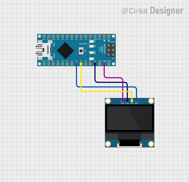
Circuit Documentation
Summary
This document provides a detailed overview of a simple circuit involving an Arduino Nano microcontroller and a 0.96" OLED display. The Arduino Nano is used to control the OLED display via I2C communication. The document includes a list of components, wiring details, and the code used in the microcontroller.
Component List
0.96" OLED
- Description: A small OLED display used for visual output.
- Pins: GND, VDD, SCK, SDA
- Purpose in Circuit: Display information controlled by the Arduino Nano.
Arduino Nano
- Description: A compact microcontroller board based on the ATmega328P.
- Pins: D1/TX, D0/RX, RESET, GND, D2, D3, D4, D5, D6, D7, D8, D9, D10, D11/MOSI, D12/MISO, VIN, 5V, A7, A6, A5, A4, A3, A2, A1, A0, AREF, 3V3, D13/SCK
- Purpose in Circuit: Control the OLED display and execute the embedded code.
Wiring Details
0.96" OLED
- GND connected to Arduino Nano GND
- VDD connected to Arduino Nano 5V
- SCK connected to Arduino Nano A5
- SDA connected to Arduino Nano A4
Arduino Nano
- GND connected to 0.96" OLED GND
- 5V connected to 0.96" OLED VDD
- A5 connected to 0.96" OLED SCK
- A4 connected to 0.96" OLED SDA
Code
Arduino Nano Code (sketch.ino)
void setup() {
  // put your setup code here, to run once:

}

void loop() {
  // put your main code here, to run repeatedly:

}
Documentation (documentation.txt)
This document provides a comprehensive overview of the circuit, including the components used, their wiring, and the code running on the Arduino Nano. This setup allows for basic control and display functionality using the OLED screen.