Arduino UNO-Based Automation System with IR Sensors and Motor Control
Circuit Documentation
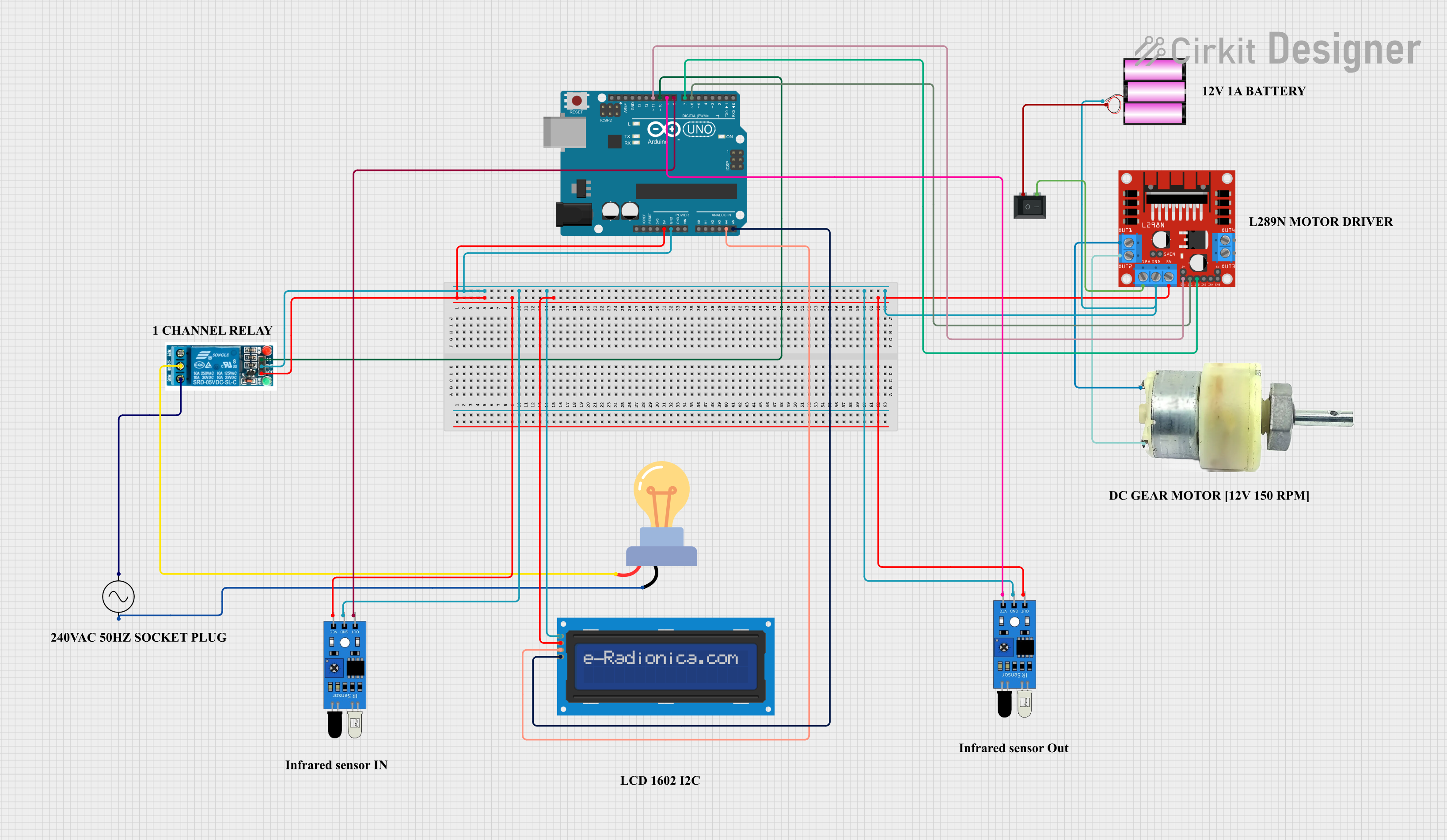
Summary
This circuit is designed to control a 12V geared motor and an LED bulb using an Arduino UNO microcontroller. The circuit includes an LCD screen for display purposes, two IR sensors for input, a 5V relay to switch the AC-powered LED bulb, and an L298N motor driver to control the motor. The system is powered by a 12V battery, and a rocker switch is used to control the power supply to the motor driver. The Arduino UNO manages the inputs and outputs, interfacing with the IR sensors, the LCD screen, and controlling the relay and motor driver.
Component List
Arduino UNO
- Microcontroller board based on the ATmega328P
- Provides digital and analog I/O pins
- Powers certain components in the circuit and provides ground connections
- Interfaces with the LCD screen via I2C communication
- Controls the relay and motor driver through digital outputs
LCD screen 16x2 I2C
- Alphanumeric liquid crystal display
- Displays information to the user
- Uses I2C communication for interfacing with the Arduino UNO
IR Sensor
- Infrared sensor for detecting objects or motion
- Provides digital output to the Arduino UNO
12V Geared Motor
- Electric motor with a gearbox for increased torque
- Powered and controlled by the L298N motor driver
L298N DC Motor Driver
- H-Bridge motor driver module
- Controls the direction and speed of the motor
- Receives control signals from the Arduino UNO
5V Relay
- Electromechanical switch
- Controls the AC circuit of the LED bulb
- Activated by a digital output from the Arduino UNO
Battery 12V
- Provides power to the motor driver and indirectly to the motor
AC Supply
- Provides alternating current to the LED bulb
- Controlled by the relay
LED Bulb AC
- Light-emitting diode bulb for AC circuits
- Switched on and off by the relay
Rocker Switch (SPST)
- Single Pole Single Throw switch
- Controls the connection between the battery and the motor driver
Wiring Details
Arduino UNO
5Vpin connected to the VCC of the relay, IR sensor, LCD screen, and motor driverGNDpin connected to the GND of the relay, IR sensor, LCD screen, motor driver, and batteryA4(SDA) pin connected to the SDA pin of the LCD screenA5(SCL) pin connected to the SCL pin of the LCD screenD11pin connected to the ENA pin of the motor driverD10pin connected to the In pin of the relayD9pin connected to the VCC pin of the IR sensorD8pin connected to the OUT pin of the IR sensorD7pin connected to the IN2 pin of the motor driverD6pin connected to the IN1 pin of the motor driver
LCD screen 16x2 I2C
SDApin connected to the SDA (A4) pin of the Arduino UNOSCLpin connected to the SCL (A5) pin of the Arduino UNOVCCpin connected to the 5V pin of the Arduino UNOGNDpin connected to the GND pin of the Arduino UNO
IR Sensor
VCCpin connected to the 5V pin of the Arduino UNOGNDpin connected to the GND pin of the Arduino UNOOUTpin connected to the D8 pin of the Arduino UNO
12V Geared Motor
Terminal 1connected to the OUT1 pin of the motor driverTerminal 2connected to the OUT2 pin of the motor driver
L298N DC Motor Driver
ENApin connected to the D11 pin of the Arduino UNOIN1pin connected to the D6 pin of the Arduino UNOIN2pin connected to the D7 pin of the Arduino UNOOUT1andOUT2pins connected to the terminals of the 12V geared motor12Vpin connected to the 2 pin of the rocker switchGNDpin connected to the GND pin of the Arduino UNO
5V Relay
VCCpin connected to the 5V pin of the Arduino UNOGNDpin connected to the GND pin of the Arduino UNOInpin connected to the D10 pin of the Arduino UNOCommon terminalconnected to the + pin of the LED bulbNormally Closedconnected to the +ve pin of the AC supply
Battery 12V
+pin connected to the 1 pin of the rocker switch-pin connected to the GND pin of the Arduino UNO
AC Supply
+vepin connected to the Normally Closed pin of the relay-vepin connected to the - pin of the LED bulb
LED Bulb AC
+pin connected to the Common terminal pin of the relay-pin connected to the -ve pin of the AC supply
Rocker Switch (SPST)
1pin connected to the + pin of the battery2pin connected to the 12V pin of the motor driver
Documented Code
Arduino UNO Code (sketch.ino)
void setup() {
  // put your setup code here, to run once:

}

void loop() {
  // put your main code here, to run repeatedly:

}
Note: The provided code is a template and does not contain any functional code. It needs to be populated with the logic to control the relay, read the IR sensors, display data on the LCD, and control the motor driver.