
Circuit Documentation
Summary
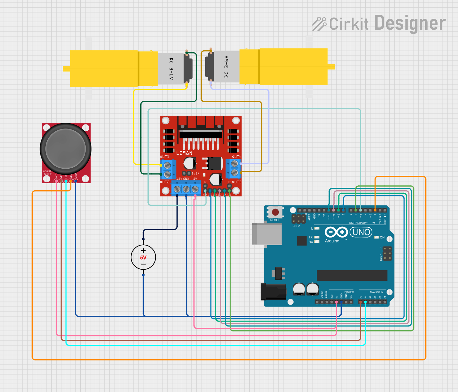
This circuit is designed to control a two-wheel car using an L298N motor driver and an analog joystick. The joystick allows for intuitive control of the car's movement and direction. The L298N motor driver interfaces with two DC gear motors, enabling forward, backward, and turning movements based on the joystick's position.
Component List
L298N Motor Driver
- Description: A dual H-bridge motor driver that allows control of two DC motors.
- Purpose: To drive the DC gear motors based on control signals from the Arduino.
5V DC Power Supply
- Description: A power supply that provides a stable 5V output.
- Purpose: To power the Arduino and the L298N motor driver.
Arduino UNO
- Description: A microcontroller board based on the ATmega328P.
- Purpose: To process inputs from the joystick and control the motor driver.
DC Gear Motor (3-6V)
- Description: A small DC motor with a gear reduction for increased torque.
- Purpose: To provide movement for the two-wheel car.
Analog Joystick
- Description: A joystick module that provides analog output for two axes and a button.
- Purpose: To allow user input for controlling the direction and movement of the car.
Wiring Details
L298N Motor Driver
- 12V connected to Positive of the 5V DC Power Supply
- GND connected to Negative of the 5V DC Power Supply
- 5V connected to 5V of the Arduino
- OUT1 connected to V+ of the first DC Gear Motor
- OUT2 connected to V- of the first DC Gear Motor
- OUT3 connected to V+ of the second DC Gear Motor
- OUT4 connected to V- of the second DC Gear Motor
- ENA connected to D5 of the Arduino
- IN1 connected to D8 of the Arduino
- IN2 connected to D9 of the Arduino
- IN3 connected to D10 of the Arduino
- IN4 connected to D11 of the Arduino
- ENB connected to D6 of the Arduino
5V DC Power Supply
- Positive connected to 12V of the L298N Motor Driver
- Negative connected to GND of the Arduino, L298N Motor Driver, and Analog Joystick
Arduino UNO
- 5V connected to 5V of the L298N Motor Driver and VCC of the Analog Joystick
- GND connected to Negative of the 5V DC Power Supply and GND of the L298N Motor Driver and Analog Joystick
- D5 connected to ENA of the L298N Motor Driver
- D8 connected to IN1 of the L298N Motor Driver
- D9 connected to IN2 of the L298N Motor Driver
- D10 connected to IN3 of the L298N Motor Driver
- D11 connected to IN4 of the L298N Motor Driver
- D6 connected to ENB of the L298N Motor Driver
- A0 connected to VERT of the Analog Joystick
- A1 connected to HORZ of the Analog Joystick
- D2 connected to SEL of the Analog Joystick
DC Gear Motor (3-6V)
- V+ connected to OUT1 of the L298N Motor Driver (first motor)
- V- connected to OUT2 of the L298N Motor Driver (first motor)
DC Gear Motor (3-6V)
- V+ connected to OUT3 of the L298N Motor Driver (second motor)
- V- connected to OUT4 of the L298N Motor Driver (second motor)
Analog Joystick
- VCC connected to 5V of the Arduino
- GND connected to Negative of the 5V DC Power Supply
- VERT connected to A0 of the Arduino
- HORZ connected to A1 of the Arduino
- SEL connected to D2 of the Arduino
Documented Code
/*
 * Arduino Sketch for controlling a two-wheel car using an L298N motor driver
 * and an analog joystick. The joystick controls the direction and movement
 * of the car. Pushing the joystick forward moves the car forward, pulling it
 * back moves it in reverse. Moving the joystick left or right turns the car
 * in the respective direction by stopping one wheel and moving the other.
 */

const int ENA = 5;  // PWM pin for left motor speed control
const int ENB = 6;  // PWM pin for right motor speed control
const int IN1 = 8;  // Direction control for left motor
const int IN2 = 9;  // Direction control for left motor
const int IN3 = 10; // Direction control for right motor
const int IN4 = 11; // Direction control for right motor

const int VERT = A0; // Joystick vertical axis
const int HORZ = A1; // Joystick horizontal axis

void setup() {
  pinMode(ENA, OUTPUT);
  pinMode(ENB, OUTPUT);
  pinMode(IN1, OUTPUT);
  pinMode(IN2, OUTPUT);
  pinMode(IN3, OUTPUT);
  pinMode(IN4, OUTPUT);

  // Initialize motors to stop
  stopMotors();
}

void loop() {
  int vertValue = analogRead(VERT);
  int horzValue = analogRead(HORZ);

  if (vertValue > 600) {
    // Move forward
    moveForward();
  } else if (vertValue < 400) {
    // Move backward
    moveBackward();
  } else if (horzValue > 600) {
    // Turn right
    turnRight();
  } else if (horzValue < 400) {
    // Turn left
    turnLeft();
  } else {
    // Stop
    stopMotors();
  }
}

void moveForward() {
  digitalWrite(IN1, HIGH);
  digitalWrite(IN2, LOW);
  digitalWrite(IN3, HIGH);
  digitalWrite(IN4, LOW);
  analogWrite(ENA, 255);
  analogWrite(ENB, 255);
}

void moveBackward() {
  digitalWrite(IN1, LOW);
  digitalWrite(IN2, HIGH);
  digitalWrite(IN3, LOW);
  digitalWrite(IN4, HIGH);
  analogWrite(ENA, 255);
  analogWrite(ENB, 255);
}

void turnRight() {
  digitalWrite(IN1, HIGH);
  digitalWrite(IN2, LOW);
  digitalWrite(IN3, LOW);
  digitalWrite(IN4, LOW);
  analogWrite(ENA, 255);
  analogWrite(ENB, 0);
}

void turnLeft() {
  digitalWrite(IN1, LOW);
  digitalWrite(IN2, LOW);
  digitalWrite(IN3, HIGH);
  digitalWrite(IN4, LOW);
  analogWrite(ENA, 0);
  analogWrite(ENB, 255);
}

void stopMotors() {
  digitalWrite(IN1, LOW);
  digitalWrite(IN2, LOW);
  digitalWrite(IN3, LOW);
  digitalWrite(IN4, LOW);
  analogWrite(ENA, 0);
  analogWrite(ENB, 0);
}
This documentation provides a comprehensive overview of the circuit, detailing each component, its wiring, and the code used to control the system.