Arduino and ESP32 Based Touch and Capacitive Sensor Ignition System
Circuit Documentation
Summary
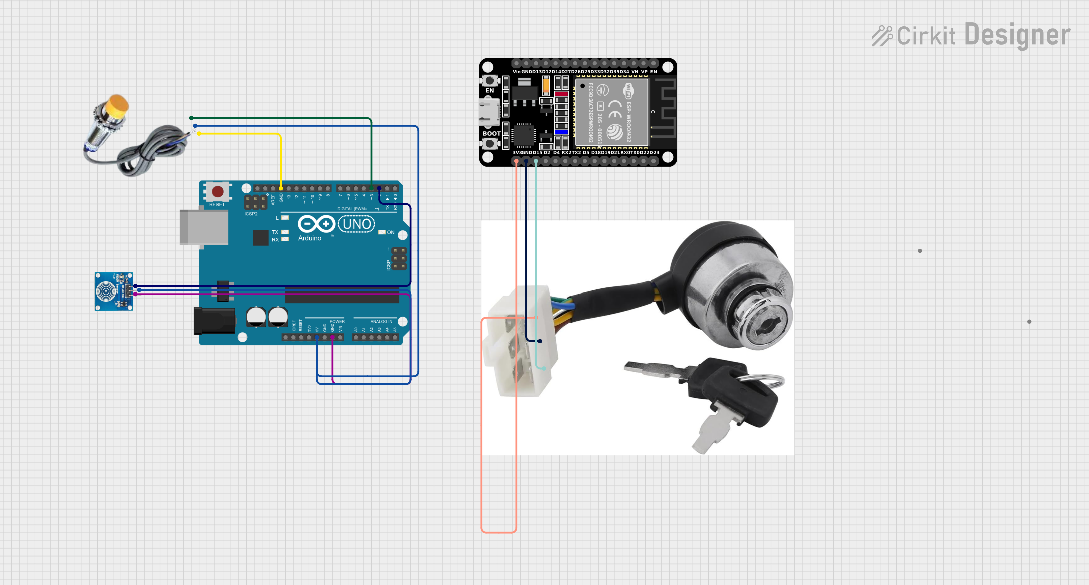
The circuit in question is designed to interface an Arduino UNO with a capacitive sensor and a touch sensor. The Arduino reads the state of these sensors and communicates with an ESP32 microcontroller. The ESP32 is responsible for controlling an ignition switch based on the data received from the Arduino. The communication between the Arduino and the ESP32 can be established via Wi-Fi or Bluetooth, depending on the requirements of the project. The ESP32 also manages the power state of the ignition switch.
Component List
Arduino UNO
- Description: A microcontroller board based on the ATmega328P.
- Purpose: Reads sensor data and sends it to the ESP32.
Capacitive Sensor
- Description: A sensor that detects touch or proximity.
- Purpose: Provides input to the Arduino regarding touch or proximity events.
Touch Sensor
- Description: A sensor that detects physical touch.
- Purpose: Provides input to the Arduino regarding touch events.
ESP32 (30 pin)
- Description: A microcontroller with Wi-Fi and Bluetooth capabilities.
- Purpose: Receives sensor data from the Arduino and controls the ignition switch.
Ignition Switch
- Description: A switch that controls the ignition circuit.
- Purpose: Is controlled by the ESP32 to turn on or off the ignition circuit.
Wiring Details
Arduino UNO
- GND: Connected to the GND pin of the Capacitive Sensor and the GND pin of the Touch Sensor.
- 5V: Powers the Capacitive Sensor and the Touch Sensor.
- D3: Receives the SIGNAL from the Capacitive Sensor.
- D2: Receives the IO signal from the Touch Sensor.
Capacitive Sensor
- GND: Connected to the GND pin on the Arduino UNO.
- VCC: Powered by the 5V pin on the Arduino UNO.
- SIGNAL: Sends the signal to the D3 pin on the Arduino UNO.
Touch Sensor
- IO: Sends the touch signal to the D2 pin on the Arduino UNO.
- VCC: Powered by the 5V pin on the Arduino UNO.
- GND: Connected to the GND pin on the Arduino UNO.
ESP32 (30 pin)
- D15: Receives the SIG signal from the Ignition Switch.
- GND: Connected to the gnd pin of the Ignition Switch.
- 3V3: Powers the Ignition Switch.
Ignition Switch
- SIG: Sends the signal to the D15 pin on the ESP32.
- gnd: Connected to the GND pin on the ESP32.
- vcc: Powered by the 3V3 pin on the ESP32.
Documented Code
Arduino Code
#include <WiFiNINA.h>
#include <WiFiClient.h>

const char* ssid = "your_SSID";
const char* password = "your_PASSWORD";
const char* serverIP = "ESP32_IP_ADDRESS";

WiFiClient client;

const int touchPin = 2; // D2
const int capacitivePin = 3; // D3

void setup() {
  Serial.begin(115200);
  pinMode(touchPin, INPUT);
  pinMode(capacitivePin, INPUT);

  while (WiFi.begin(ssid, password) != WL_CONNECTED) {
    delay(1000);
    Serial.println("Connecting to WiFi...");
  }

  Serial.println("Connected to WiFi");
}

void loop() {
  int touchState = digitalRead(touchPin);
  int capacitiveState = digitalRead(capacitivePin);

  if (client.connect(serverIP, 80)) {
    client.print("GET /update?touch=");
    client.print(touchState);
    client.print("&capacitive=");
    client.print(capacitiveState);
    client.println(" HTTP/1.1");
    client.println("Host: ESP32_IP_ADDRESS");
    client.println("Connection: close");
    client.println();
  }

  delay(1000); // Adjust the delay as needed
}
ESP32 Code
#include <WiFi.h>
#include <WebServer.h>

const char* ssid = "your_SSID";
const char* password = "your_PASSWORD";

WebServer server(80);

const int ignitionPin = 15; // D15

void handleUpdate() {
  String touchState = server.arg("touch");
  String capacitiveState = server.arg("capacitive");

  if (touchState == "1" && capacitiveState == "1") {
    digitalWrite(ignitionPin, HIGH);
  } else {
    digitalWrite(ignitionPin, LOW);
  }

  server.send(200, "text/plain", "OK");
}

void setup() {
  Serial.begin(115200);
  pinMode(ignitionPin, OUTPUT);
  digitalWrite(ignitionPin, LOW);

  WiFi.begin(ssid, password);

  while (WiFi.status() != WL_CONNECTED) {
    delay(1000);
    Serial.println("Connecting to WiFi...");
  }

  Serial.println("Connected to WiFi");
  server.on("/update", handleUpdate);
  server.begin();
}

void loop() {
  server.handleClient();
}
Summary: The Arduino reads the touch and capacitive sensors and sends the data to the ESP32. The ESP32 receives the data and controls the ignition switch based on the sensor states. Choose Wi-Fi or Bluetooth based on your project requirements and adjust the code accordingly.