Arduino UNO-Based Stepper Motor Controller with Rotary Encoder and Key Switch
Circuit Documentation
Summary
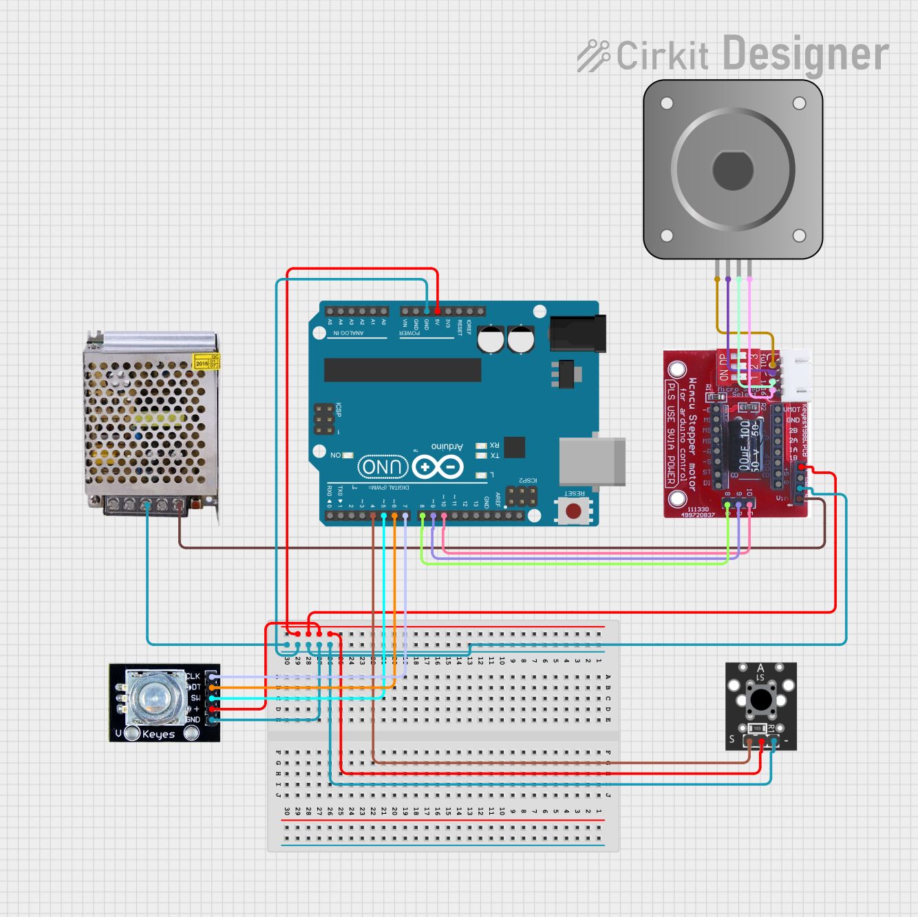
This document provides a detailed overview of a circuit designed to control a bipolar stepper motor using an Arduino UNO, a DRV8825 stepper motor driver, and various other components. The circuit includes a rotary encoder for user input and a key switch module for additional control. The power supply provides the necessary voltage and current to drive the motor and other components.
Component List
Arduino UNO
- Description: A microcontroller board based on the ATmega328P.
- Pins: UNUSED, IOREF, Reset, 3.3V, 5V, GND, Vin, A0, A1, A2, A3, A4, A5, SCL, SDA, AREF, D13, D12, D11, D10, D9, D8, D7, D6, D5, D4, D3, D2, D1, D0
DRV8825
- Description: A stepper motor driver capable of driving bipolar stepper motors.
- Pins: EN, M0, M1, M2, RST, SLP, STEP, DIR, VMOT, GND MOTOR, B2, B1, A1, A2, FAULT, GND LOGIC
A4988/DRV8825 Stepper Motor Drive Control Board/Expansion Board
- Description: An expansion board for controlling stepper motors using A4988 or DRV8825 drivers.
- Pins: Enabler, Direction, Step, V in Motor, GND Motor and Logic, Microstep 1, Microstep 2, Microstep 3, Reset, Sleep, GND Logic, Fault, 1B, 1A, 2A, 2B, GND Motor, V Motor, 5V Fault Supply
POWER SUPPLY 12V 5AMP
- Description: A power supply unit providing 12V DC at 5A.
- Pins: 220V Positive Pole (AC), 220V Negative Pole (AC), GND, GND (DC), 12V-24V Output (DC)
KY-004 Key Switch Module
- Description: A key switch module for user input.
- Pins: S, Middle, -
Rotary Encoder
- Description: A rotary encoder for user input.
- Pins: clk, dt, sw, gnd, +
Bipolar Stepper Motor (NEMA 17)
- Description: A bipolar stepper motor commonly used in 3D printers and CNC machines.
- Pins: A-, A+, B+, B-
Wiring Details
Arduino UNO
5V connected to:
- KY-004 Key Switch Module (Middle)
- Rotary Encoder (+)
- A4988/DRV8825 Stepper Motor Drive Control Board/Expansion Board (5V Fault Supply)
GND connected to:
- KY-004 Key Switch Module (-)
- Rotary Encoder (gnd)
- A4988/DRV8825 Stepper Motor Drive Control Board/Expansion Board (GND Motor and Logic)
- POWER SUPPLY 12V 5AMP (GND)
D10 connected to:
- A4988/DRV8825 Stepper Motor Drive Control Board/Expansion Board (Enabler)
D9 connected to:
- A4988/DRV8825 Stepper Motor Drive Control Board/Expansion Board (Direction)
D8 connected to:
- A4988/DRV8825 Stepper Motor Drive Control Board/Expansion Board (Step)
D7 connected to:
- Rotary Encoder (clk)
D6 connected to:
- Rotary Encoder (dt)
D5 connected to:
- Rotary Encoder (sw)
D4 connected to:
- KY-004 Key Switch Module (S)
DRV8825
- VMOT connected to:
- POWER SUPPLY 12V 5AMP (12V-24V Output (DC))
A4988/DRV8825 Stepper Motor Drive Control Board/Expansion Board
1B connected to:
- Bipolar Stepper Motor (NEMA 17) (A-)
1A connected to:
- Bipolar Stepper Motor (NEMA 17) (A+)
2A connected to:
- Bipolar Stepper Motor (NEMA 17) (B+)
2B connected to:
- Bipolar Stepper Motor (NEMA 17) (B-)
POWER SUPPLY 12V 5AMP
- 12V-24V Output (DC) connected to:
- A4988/DRV8825 Stepper Motor Drive Control Board/Expansion Board (V in Motor)
Documented Code
Arduino UNO Code (sketch.ino)
void setup() {
  // put your setup code here, to run once:

}

void loop() {
  // put your main code here, to run repeatedly:

}
Additional Documentation (documentation.txt)
This document provides a comprehensive overview of the circuit, including a detailed component list, wiring details, and documented code for the Arduino UNO.