ESP8266 NodeMCU with DHT11 Sensor and LCD Display
Circuit Documentation
Summary
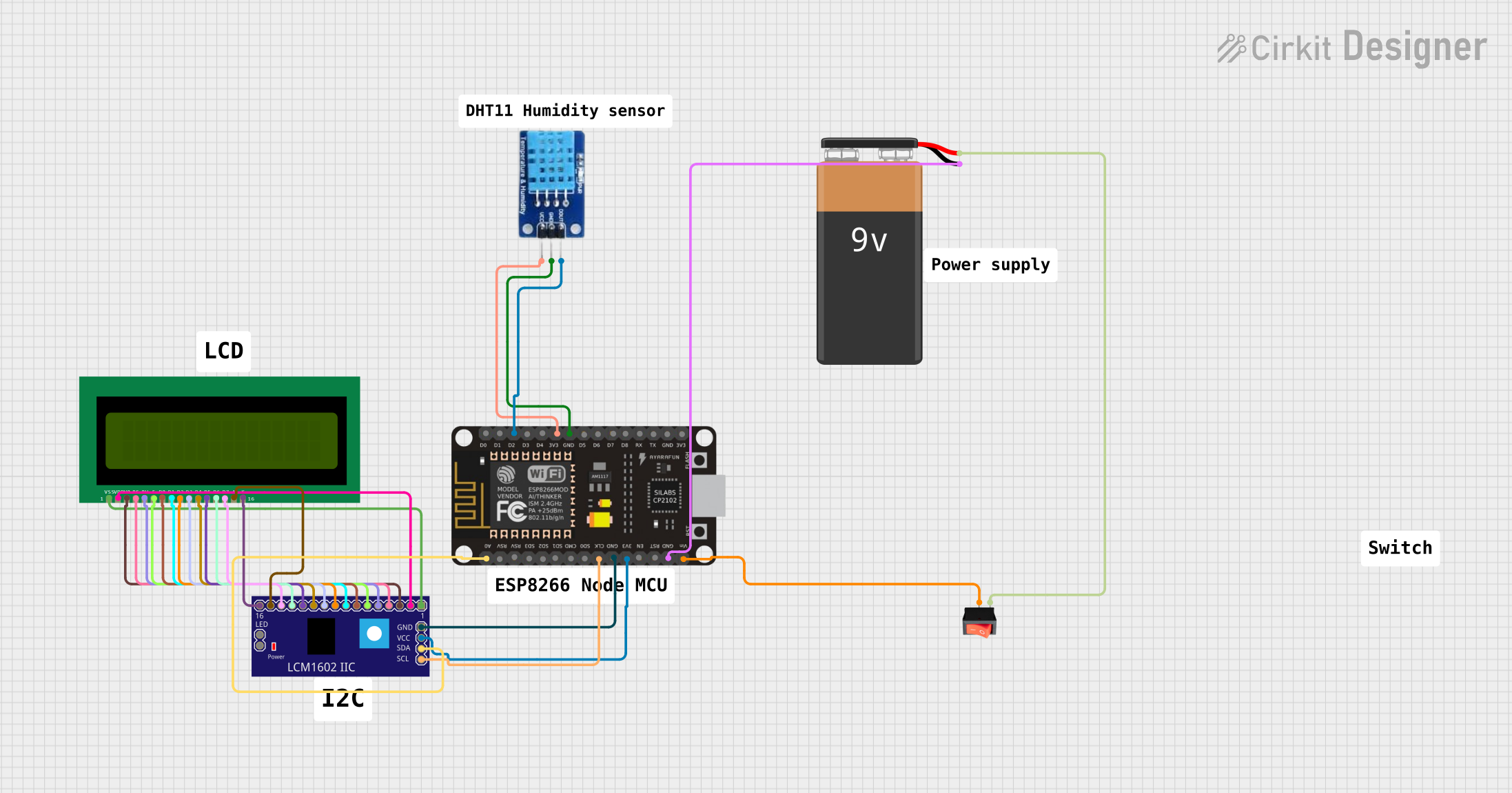
The circuit in question is designed to interface an ESP8266 NodeMCU microcontroller with a DHT11 temperature and humidity sensor and an LCM1602 IIC module connected to a 16x2 LCD display. The circuit is powered by a 9V battery, which is controlled by a rocker switch to turn the power supply on and off. The ESP8266 NodeMCU reads data from the DHT11 sensor and displays the information on the LCD through the LCM1602 IIC module. The LCD display is used to show the temperature and humidity readings to the user.
Component List
Rocker Switch
- Description: A simple on/off switch that controls the power supply to the circuit.
- Pins: output, input
DHT11
- Description: A digital temperature and humidity sensor that provides calibrated digital output.
- Pins: DATA, GND, VCC
LCM1602 IIC
- Description: An I2C interface module for 16x2 LCD displays, simplifying the number of I/O pins needed to control the LCD.
- Pins: GND, VCC, SDA, SCL, and others for direct LCD interfacing.
16X2 LCD
- Description: A liquid crystal display capable of displaying 16 characters per line across 2 lines.
- Pins: VSS, VDD, V0, RS, RW, E, D0-D7, A, K
ESP8266 NodeMCU
- Description: A Wi-Fi enabled microcontroller that is capable of executing user-defined programs and interfacing with various sensors and modules.
- Pins: D0-D8, RX, TX, A0, RSV, SD0-SD3, CMD, CLK, EN, RST, VIN, 3V3, GND
9V Battery
- Description: A standard 9V battery used to power the circuit.
- Pins: -, +
Wiring Details
Rocker Switch
- Output: Connected to the VIN pin of the ESP8266 NodeMCU.
- Input: Connected to the positive terminal of the 9V Battery.
DHT11
- DATA: Connected to the D2 pin of the ESP8266 NodeMCU.
- VCC: Connected to the 3V3 pin of the ESP8266 NodeMCU.
- GND: Connected to a GND pin of the ESP8266 NodeMCU.
LCM1602 IIC
- GND: Connected to a GND pin of the ESP8266 NodeMCU.
- VCC: Connected to the 3V3 pin of the ESP8266 NodeMCU.
- SDA: Connected to the A0 pin of the ESP8266 NodeMCU.
- SCL: Connected to the CLK pin of the ESP8266 NodeMCU.
16X2 LCD
- VSS: Connected to the VSS pin of the LCM1602 IIC.
- VDD: Connected to the VDD pin of the LCM1602 IIC.
- V0: Connected to the V0 pin of the LCM1602 IIC.
- RS: Connected to the RS pin of the LCM1602 IIC.
- RW: Connected to the RW pin of the LCM1602 IIC.
- E: Connected to the E pin of the LCM1602 IIC.
- D0-D7: Connected to the corresponding D0-D7 pins of the LCM1602 IIC.
- A: Connected to the A pin of the LCM1602 IIC.
- K: Connected to the K pin of the LCM1602 IIC.
ESP8266 NodeMCU
- D2: Connected to the DATA pin of the DHT11.
- 3V3: Connected to the VCC pins of the DHT11 and LCM1602 IIC.
- GND: Connected to the GND pins of the DHT11 and LCM1602 IIC.
- A0: Connected to the SDA pin of the LCM1602 IIC.
- CLK: Connected to the SCL pin of the LCM1602 IIC.
- VIN: Connected to the output of the rocker switch.
- GND: Connected to the negative terminal of the 9V Battery.
9V Battery
- +: Connected to the input of the rocker switch.
- -: Connected to a GND pin of the ESP8266 NodeMCU.
Documented Code
Since no code was provided in the input, this section is not applicable. However, the expected code for the ESP8266 NodeMCU would typically initialize the DHT11 sensor, read temperature and humidity data, and then send this data to the LCD display via the LCM1602 IIC module. The code would also handle any necessary Wi-Fi communication if the ESP8266 NodeMCU is used to send data to a remote server or service.