
Arduino Mega 2560-Based Battery-Powered Robotic Vehicle with Ultrasonic Sensor and Motor Driver Shield
View and Edit Project In Cirkit Designer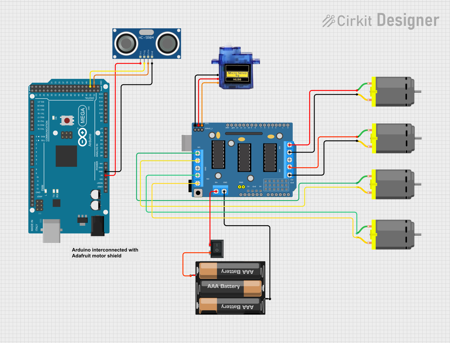
Circuit Documentation
Summary
This document provides a detailed overview of a circuit that includes an Arduino Mega 2560, a DRIVER SHIELD L293D, multiple DC motors, a micro servo, an ultrasonic sensor, a battery pack, and a rocker switch. The circuit is designed to control the motors and servo, and to read distance measurements from the ultrasonic sensor. The Arduino Mega 2560 serves as the main microcontroller, running the embedded code to control the various components.
Component List
Arduino Mega 2560
- Description: A microcontroller board based on the ATmega2560.
- Pins: IOREF, RESET, 3V3, 5V, GND, VIN, A0-A15, D21/SCL, D20/SDA, D19/RX1, D18/TX1, D17 PWM/RX2, D16 PWM/TX2, D15/RX3, D14/TX3, D0 RX0, D1 TX0, D2-D13 PWM, AREF, SDA, SCL, D22-D53.
DRIVER SHIELD L293D
- Description: A motor driver shield capable of driving four DC motors or two stepper motors.
- Pins: RESET, 3.3V, 5V, GND, VIN, 9V, A0-A5, M1-M4 (+/-), SERVO_1, SERVO_2, RX/D0, TX/D1, D2-D13, ARef, VCC (External Power Supply), GND (External Power Supply).
Micro Servo 9G
- Description: A small servo motor used for precise control of angular position.
- Pins: GND, +5V, PWM.
DC Motor
- Description: A simple DC motor.
- Pins: pin 1, pin 2.
3xAA Battery
- Description: A battery pack holding three AA batteries.
- Pins: VCC, GND.
HC-SR04 Ultrasonic Sensor
- Description: An ultrasonic sensor used for distance measurement.
- Pins: VCC, TRIG, ECHO, GND.
Rocker Switch (SPST)
- Description: A single-pole single-throw (SPST) rocker switch.
- Pins: 1, 2.
Wiring Details
Arduino Mega 2560
- 5V connected to VCC of HC-SR04 Ultrasonic Sensor.
- GND connected to GND of HC-SR04 Ultrasonic Sensor.
- D53 connected to ECHO of HC-SR04 Ultrasonic Sensor.
- D51 connected to TRIG of HC-SR04 Ultrasonic Sensor.
DRIVER SHIELD L293D
- M2 (+) connected to pin 2 of DC Motor.
- M2 GND (-) connected to pin 1 of DC Motor.
- M1 (+) connected to pin 1 of DC Motor.
- M1 GND (-) connected to pin 2 of DC Motor.
- M3 (+) connected to pin 2 of DC Motor.
- M3 GND (-) connected to pin 1 of DC Motor.
- M4 GND (-) connected to pin 2 of DC Motor.
- M4 (+) connected to pin 1 of DC Motor.
- GND connected to GND of Micro Servo 9G.
- 5V connected to +5V of Micro Servo 9G.
- SERVO_1 connected to PWM of Micro Servo 9G.
- VCC (External Power Supply) connected to pin 2 of Rocker Switch (SPST).
- GND (External Power Supply) connected to GND of 3xAA Battery.
Micro Servo 9G
- GND connected to GND of DRIVER SHIELD L293D.
- +5V connected to 5V of DRIVER SHIELD L293D.
- PWM connected to SERVO_1 of DRIVER SHIELD L293D.
DC Motor
- pin 2 connected to M2 (+) of DRIVER SHIELD L293D.
- pin 1 connected to M2 GND (-) of DRIVER SHIELD L293D.
- pin 1 connected to M1 (+) of DRIVER SHIELD L293D.
- pin 2 connected to M1 GND (-) of DRIVER SHIELD L293D.
- pin 2 connected to M3 (+) of DRIVER SHIELD L293D.
- pin 1 connected to M3 GND (-) of DRIVER SHIELD L293D.
- pin 2 connected to M4 GND (-) of DRIVER SHIELD L293D.
- pin 1 connected to M4 (+) of DRIVER SHIELD L293D.
3xAA Battery
- GND connected to GND (External Power Supply) of DRIVER SHIELD L293D.
- VCC connected to pin 1 of Rocker Switch (SPST).
HC-SR04 Ultrasonic Sensor
- VCC connected to 5V of Arduino Mega 2560.
- GND connected to GND of Arduino Mega 2560.
- ECHO connected to D53 of Arduino Mega 2560.
- TRIG connected to D51 of Arduino Mega 2560.
Rocker Switch (SPST)
- pin 2 connected to VCC (External Power Supply) of DRIVER SHIELD L293D.
- pin 1 connected to VCC of 3xAA Battery.
Documented Code
Arduino Mega 2560 Code
void setup() {
  // put your setup code here, to run once:

}

void loop() {
  // put your main code here, to run repeatedly:

}
This code is a basic template for the Arduino Mega 2560. The setup() function is where you initialize your components and the loop() function is where you place the main code that runs repeatedly.