
Raspberry Pi 4B Motion-Activated Alarm System with LED Indicator
View and Edit Project In Cirkit Designer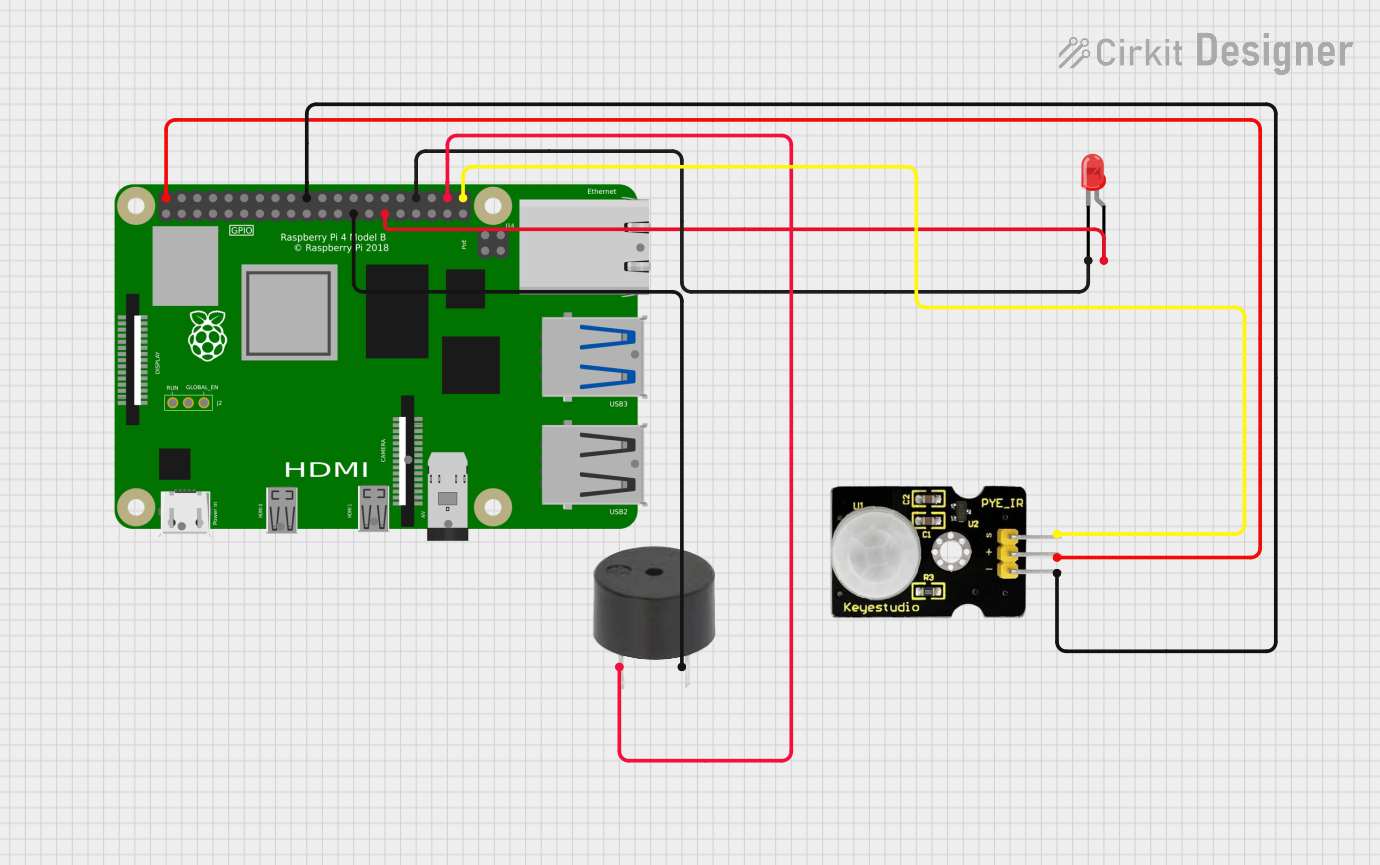
Circuit Documentation
Summary
This document provides a detailed overview of a circuit that includes a Raspberry Pi 4B, a red LED, a PIR sensor, and a buzzer. The Raspberry Pi 4B serves as the central controller, interfacing with the other components to create a functional system. The PIR sensor detects motion, the LED provides visual feedback, and the buzzer provides auditory feedback.
Component List
Raspberry Pi 4B
- Description: A powerful single-board computer used for various applications.
- Pins: 3V3, 5V, GPIO2, GPIO3, GND, GPIO4, GPIO14, GPIO15, GPIO17, GPIO18, GPIO27, GPIO22, GPIO23, GPIO24, GPIO10, GPIO9, GPIO25, GPIO11, GPIO8, GPIO7, ID_SD, GPIO5, GPIO6, GPIO12, GPIO13, GPIO19, GPIO16, GPIO26, GPIO20, GPIO21, ID_SC, TR01_TAP, TR00_TAP, TR03_TAP, TR02_TAP, RUN, GLOBAL_EN, ETH, HDMI 0, HDMI 1, CAMERA, AV
LED: Two Pin (red)
- Description: A red LED used for visual indication.
- Pins: cathode, anode
PIR Sensor
- Description: A sensor used to detect motion.
- Pins: GND, VCC, Data
Buzzer
- Description: A buzzer used for auditory feedback.
- Pins: PIN, GND
Wiring Details
Raspberry Pi 4B
- 5V is connected to VCC of the PIR Sensor.
- GND is connected to:
- GND of the PIR Sensor.
- GND of the Buzzer.
- cathode of the LED.
- GPIO5 is connected to anode of the LED.
- GPIO20 is connected to PIN of the Buzzer.
- GPIO21 is connected to Data of the PIR Sensor.
LED: Two Pin (red)
- anode is connected to GPIO5 of the Raspberry Pi 4B.
- cathode is connected to GND of the Raspberry Pi 4B.
PIR Sensor
- VCC is connected to 5V of the Raspberry Pi 4B.
- GND is connected to GND of the Raspberry Pi 4B.
- Data is connected to GPIO21 of the Raspberry Pi 4B.
Buzzer
- PIN is connected to GPIO20 of the Raspberry Pi 4B.
- GND is connected to GND of the Raspberry Pi 4B.
Code
No code is provided for this circuit.
This document provides a comprehensive overview of the circuit, including a summary, detailed component list, wiring details, and code documentation. This should serve as a useful reference for understanding and replicating the circuit.