
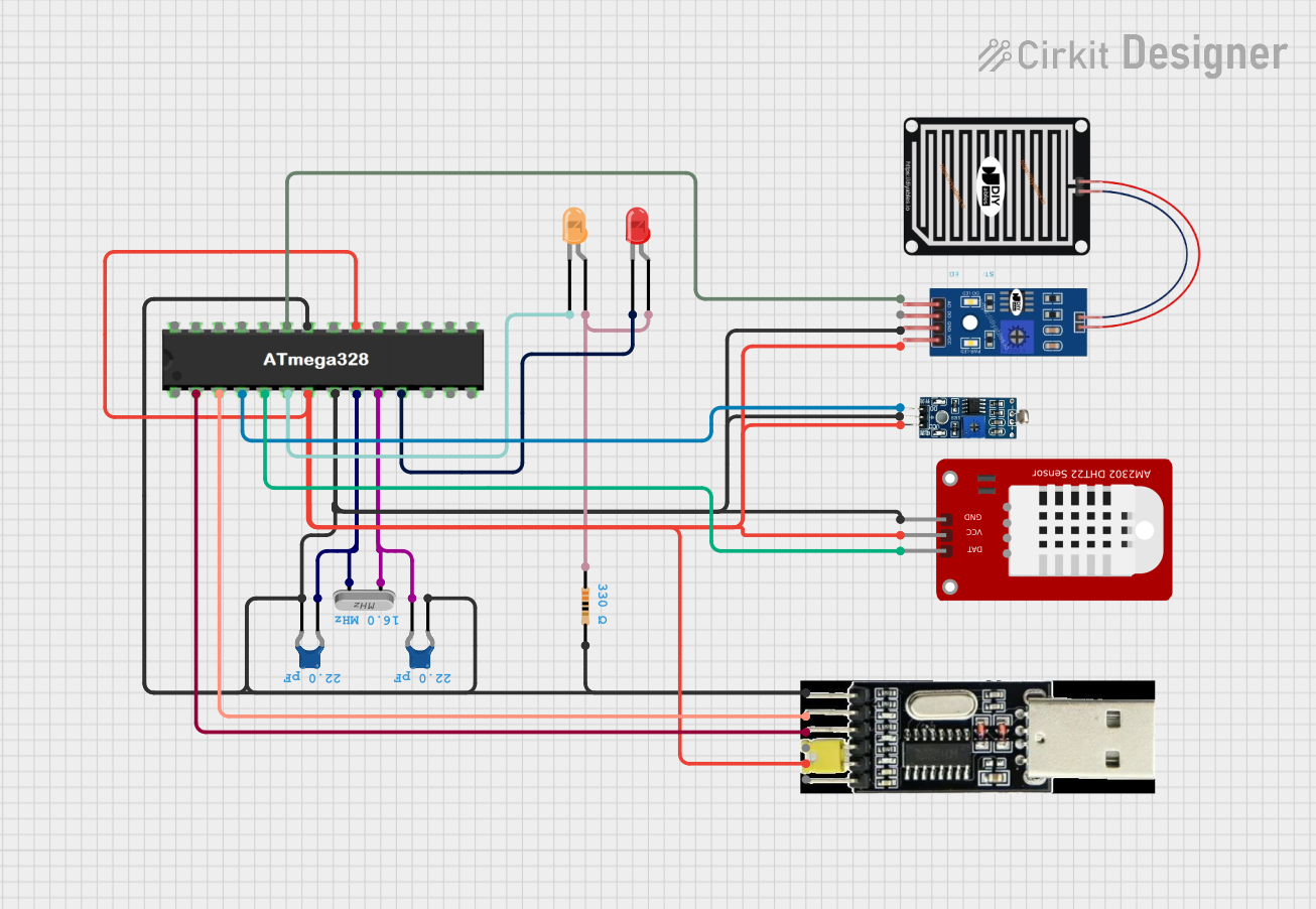
Circuit Documentation
Summary
This document provides a detailed overview of a circuit design that includes various components such as capacitors, crystals, LEDs, sensors, and a microcontroller. The circuit is designed to interface with multiple sensors and indicators, with the ATMEGA328 microcontroller serving as the central control unit. The document includes a component list, wiring details, and code documentation.
Component List
Ceramic Capacitor
- Description: A capacitor with a capacitance of 22 pF.
- Pins: pin0, pin1
- Properties:
- Capacitance: 22 pF
Crystal
- Description: A crystal oscillator.
- Pins: pin 0, pin 1
LED: Two Pin (red)
- Description: A red LED.
- Pins: cathode, anode
LED: Two Pin (orange)
- Description: An orange LED.
- Pins: cathode, anode
LDR Module 3 pin
- Description: A light-dependent resistor module.
- Pins: VCC, GND, DO
RAIN SENSOR
- Description: A rain sensor module.
- Pins: AO, DO, GRD, VCC
ATMEGA328
- Description: A microcontroller.
- Pins: RESET, D0, D1, D2, D3, D4, VCC, GND, CRYSTAL, D5, D6, D7, D8, D9, D10, D11, D12, D13, AREF, A0, A1, A2, A3, A4, A5
DHT22
- Description: A temperature and humidity sensor.
- Pins: GND, VCC, DAT
CH 34O TTL
- Description: A USB to TTL serial converter.
- Pins: GND, RXD, TXD, 5V, VCC, 3V3
Resistor
- Description: A resistor with a resistance of 330 Ohms.
- Pins: pin1, pin2
- Properties:
- Resistance: 330 Ohms
Wiring Details
Ceramic Capacitor
Capacitor 1:
- pin0: Connected to GND
- pin1: Connected to CRYSTAL pin of ATMEGA328 and pin 0 of Crystal
Capacitor 2:
- pin0: Connected to pin 1 of Crystal
- pin1: Connected to GND
Crystal
- pin 0: Connected to CRYSTAL pin of ATMEGA328 and pin1 of Ceramic Capacitor 1
- pin 1: Connected to CRYSTAL pin of ATMEGA328 and pin0 of Ceramic Capacitor 2
LED: Two Pin (red)
- cathode: Connected to D5 pin of ATMEGA328
- anode: Connected to pin1 of Resistor
LED: Two Pin (orange)
- cathode: Connected to D4 pin of ATMEGA328
- anode: Connected to pin1 of Resistor
LDR Module 3 pin
- VCC: Connected to VCC
- GND: Connected to GND
- DO: Connected to D2 pin of ATMEGA328
RAIN SENSOR
- AO: Connected to A0 pin of ATMEGA328
- DO: Not connected
- GRD: Connected to GND
- VCC: Connected to VCC
ATMEGA328
- RESET: Not connected
- D0: Connected to TXD pin of CH 34O TTL
- D1: Connected to RXD pin of CH 34O TTL
- D2: Connected to DO pin of LDR Module 3 pin
- D3: Connected to DAT pin of DHT22
- D4: Connected to cathode of LED: Two Pin (orange)
- D5: Connected to cathode of LED: Two Pin (red)
- VCC: Connected to VCC
- GND: Connected to GND
- CRYSTAL: Connected to pin 0 and pin 1 of Crystal
- A0: Connected to AO pin of RAIN SENSOR
DHT22
- GND: Connected to GND
- VCC: Connected to VCC
- DAT: Connected to D3 pin of ATMEGA328
CH 34O TTL
- GND: Connected to GND
- RXD: Connected to D1 pin of ATMEGA328
- TXD: Connected to D0 pin of ATMEGA328
- 5V: Not connected
- VCC: Connected to VCC
- 3V3: Not connected
Resistor
- pin1: Connected to anode of LED: Two Pin (orange) and anode of LED: Two Pin (red)
- pin2: Connected to GND
Code Documentation
No code is provided for this circuit.
This document provides a comprehensive overview of the circuit, including a detailed list of components and their wiring connections. This should serve as a useful reference for understanding and replicating the circuit design.