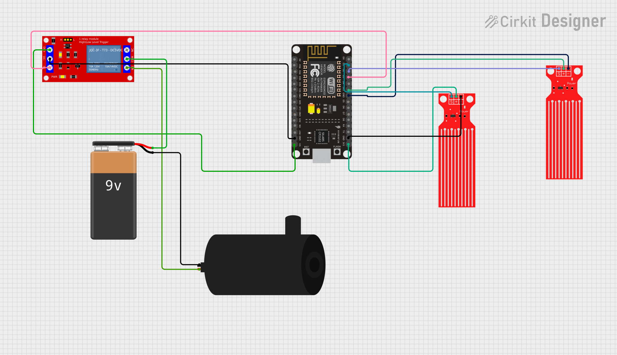
ESP8266 NodeMCU Automated Water Tank Filling System

Automatic Tank Filling System Documentation
Summary
The Automatic Tank Filling System is designed to control a water pump using an ESP8266 NodeMCU microcontroller. The system incorporates two water level sensors to monitor the water level within a tank. The pump is managed based on the feedback from these sensors: it is turned off when both sensors detect water, and it is turned on when neither sensor detects water. A relay module is used to control the high-power circuit of the water pump, which is powered by a 9V battery.
Component List
ESP8266 NodeMCU
- Microcontroller with WiFi capability.
- Pins: D0, D1, D2, D3, D4, 3V3, GND, D5, D6, D7, D8, RX, TX, A0, RSV, SD3, SD2, SD1, CMD, SD0, CLK, EN, RST, VIN.
Water Level Sensor (x2)
- Sensor for detecting water level.
- Pins: SIG, VCC, GND.
1 Channel 5V Relay Module
- Module for controlling high power devices.
- Pins: VCC+, VCC- (GND), IN, N.O., COM, N.C.
9V Battery
- Power source for the water pump.
- Pins: -, +.
Water Pump
- Pump for moving water.
- Pins: positive, negative.
Wiring Details
ESP8266 NodeMCU
- D1 connected to High Water Level Sensor SIG.
- D2 connected to Low Water Level Sensor SIG.
- D3 connected to Relay Module IN.
- 3V3 connected to both Water Level Sensors VCC.
- GND connected to both Water Level Sensors GND and Relay Module VCC- (GND).
- VIN connected to Relay Module VCC+.
Water Level Sensors
- SIG of High Water Level Sensor connected to ESP8266 NodeMCU D1.
- SIG of Low Water Level Sensor connected to ESP8266 NodeMCU D2.
- VCC of both sensors connected to ESP8266 NodeMCU 3V3.
- GND of both sensors connected to ESP8266 NodeMCU GND.
1 Channel 5V Relay Module
- IN connected to ESP8266 NodeMCU D3.
- VCC+ connected to ESP8266 NodeMCU VIN.
- VCC- (GND) connected to ESP8266 NodeMCU GND.
- N.O. connected to Water Pump positive.
- COM connected to 9V Battery +.
9V Battery
- connected to Relay Module COM.
- connected to Water Pump negative.
Water Pump
- Positive connected to Relay Module N.O.
- Negative connected to 9V Battery -.
Documented Code
/*
 * Automatic Tank Filling System
 * This code controls a water pump using an ESP8266 NodeMCU. The system uses two
 * water level sensors to detect the water level in a tank. When both sensors
 * detect water, the pump is turned off. When neither sensor detects water, the
 * pump is turned on.
 */

#include <Arduino.h>

const int lowSensorPin = 4;  // Low water level sensor connected to D2 (GPIO4)
const int highSensorPin = 5; // High water level sensor connected to D1 (GPIO5)
const int relayPin = 0;      // Relay module connected to D3 (GPIO0)

void setup() {
  pinMode(lowSensorPin, INPUT);  // Set low sensor pin as input
  pinMode(highSensorPin, INPUT); // Set high sensor pin as input
  pinMode(relayPin, OUTPUT);     // Set relay pin as output
  digitalWrite(relayPin, LOW);   // Initialize relay to off
}

void loop() {
  bool lowSensorState = digitalRead(lowSensorPin);  // Read low sensor state
  bool highSensorState = digitalRead(highSensorPin); // Read high sensor state

  if (lowSensorState == HIGH && highSensorState == HIGH) {
    digitalWrite(relayPin, LOW);  // Turn off pump if both sensors detect water
  } else if (lowSensorState == LOW && highSensorState == LOW) {
    digitalWrite(relayPin, HIGH); // Turn on pump if neither sensor detects water
  }

  delay(1000); // Wait for 1 second before next reading
}
This code is designed to be uploaded to the ESP8266 NodeMCU. It initializes the pins connected to the water level sensors and the relay module. In the main loop, it reads the state of both water level sensors and controls the relay accordingly, which in turn controls the water pump.