Wi-Fi Controlled Quad DC Motor Driver System
Circuit Documentation
Summary
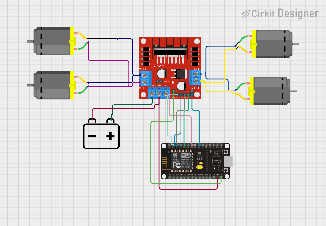
This circuit is designed to control multiple DC motors using an ESP8266 NodeMCU microcontroller and an L298N DC motor driver. The ESP8266 NodeMCU interfaces with the L298N motor driver to control the speed and direction of the motors. A 12V battery provides the power source for the motors and the motor driver, while the ESP8266 is powered through its VIN pin, presumably from a regulated 5V supply that is also provided by the L298N motor driver.
Component List
DC Motor
- Description: A standard DC motor used for converting electrical energy into mechanical rotation.
- Pins: pin 1, pin 2
L298N DC Motor Driver
- Description: A motor driver module capable of driving up to two DC motors. It controls the direction and speed of the motors.
- Pins: OUT1, OUT2, 12V, GND, 5V, OUT3, OUT4, 5V-ENA-JMP-I, 5V-ENA-JMP-O, +5V-J1, +5V-J2, ENA, IN1, IN2, IN3, IN4, ENB
12V Battery
- Description: A power source for the circuit, providing the necessary voltage for the DC motors and the motor driver.
- Pins: -, +
ESP8266 NodeMCU
- Description: A microcontroller board with Wi-Fi capability, used for controlling the L298N motor driver.
- Pins: D0, D1, D2, D3, D4, 3V3, GND, D5, D6, D7, D8, RX, TX, A0, RSV, SD3, SD2, SD1, CMD, SD0, CLK, EN, RST, VIN
Wiring Details
DC Motors
- Motor 1:
- pin 1 connected to L298N OUT1
- pin 2 connected to L298N OUT2
- Motor 2:
- pin 1 connected to L298N OUT3
- pin 2 connected to L298N OUT4
- Motor 3:
- pin 1 connected to L298N OUT1
- pin 2 connected to L298N OUT2
- Motor 4:
- pin 1 connected to L298N OUT3
- pin 2 connected to L298N OUT4
L298N DC Motor Driver
- OUT1, OUT2 connected to DC Motor 1 and DC Motor 3
- OUT3, OUT4 connected to DC Motor 2 and DC Motor 4
- 12V connected to 12V Battery (+)
- GND connected to 12V Battery (-) and ESP8266 NodeMCU GND
- 5V-ENA-JMP-I, 5V-ENA-JMP-O not connected
- +5V-J1 connected to ESP8266 NodeMCU VIN
- +5V-J2 not connected
- ENA connected to ESP8266 NodeMCU D5
- IN1 connected to ESP8266 NodeMCU D1
- IN2 connected to ESP8266 NodeMCU D2
- IN3 connected to ESP8266 NodeMCU D3
- IN4 connected to ESP8266 NodeMCU D4
- ENB connected to ESP8266 NodeMCU D6
12V Battery
- (-) connected to ESP8266 NodeMCU GND and L298N GND
- (+) connected to L298N 12V
ESP8266 NodeMCU
- D1 connected to L298N IN1
- D2 connected to L298N IN2
- D3 connected to L298N IN3
- D4 connected to L298N IN4
- D5 connected to L298N ENA
- D6 connected to L298N ENB
- GND connected to 12V Battery (-) and L298N GND
- VIN connected to L298N +5V-J1
Documented Code
No code has been provided for the ESP8266 NodeMCU. The expected code should initialize the GPIO pins connected to the L298N motor driver and set up a communication protocol (likely over Wi-Fi) to receive control commands for the motors. The code would then translate these commands into GPIO high/low signals to control the direction and PWM signals to control the speed of the motors via the L298N driver.