
Solar-Powered Arduino Weather Station with GSM Alerts and Fire Detection
View and Edit Project In Cirkit Designer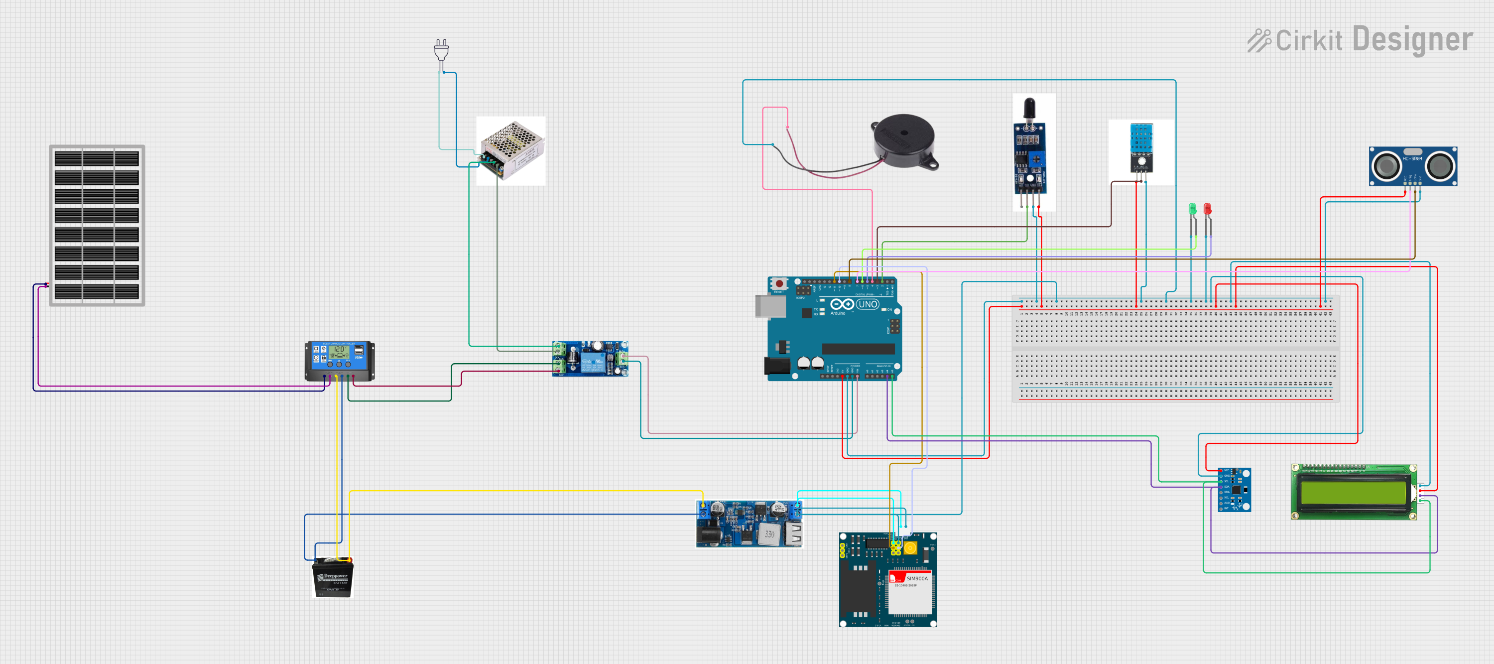
Circuit Documentation
Summary
This circuit is designed to monitor environmental parameters such as temperature, presence of fire, and water level, and to communicate alerts via SMS. It is powered by a solar panel, managed by a solar charge controller, and uses a battery for energy storage. The circuit includes an Arduino UNO microcontroller for processing sensor data and controlling peripherals like a buzzer and LEDs. A GSM module is used for sending SMS alerts. The system also includes an inverter to convert DC to AC power and a UPS module for uninterrupted power supply.
Component List
Solar Panel
- Description: A photovoltaic panel that converts sunlight into electrical energy.
- Purpose: To provide a renewable energy source for charging the battery.
Solar Charge Controller
- Description: A device that controls the charging of the battery from the solar panel and provides load management.
- Purpose: To protect the battery from overcharging and to manage power distribution.
Battery
- Description: An energy storage device.
- Purpose: To store electrical energy for use when solar power is not available.
UPS Module
- Description: An uninterruptible power supply module that provides backup power.
- Purpose: To ensure continuous operation of the circuit during power outages.
Power 220V
- Description: A source of 220V AC power.
- Purpose: To supply power to the inverter.
Inverter
- Description: A device that converts DC power from the battery to 220V AC power.
- Purpose: To provide AC power for AC-powered devices.
Arduino UNO
- Description: A microcontroller board based on the ATmega328P.
- Purpose: To control and process data from sensors and manage peripherals.
Heat Flame Sensor
- Description: A sensor that detects the presence of fire or flame.
- Purpose: To trigger an alert in case of fire.
DHT11
- Description: A basic, ultra-low-cost digital temperature and humidity sensor.
- Purpose: To measure ambient temperature and humidity.
Buzzer
- Description: An electronic sounder or speaker.
- Purpose: To provide an audible alert in case of emergency conditions.
LEDs (Green and Red)
- Description: Light-emitting diodes that emit green and red light, respectively.
- Purpose: To provide visual indicators for various statuses, such as power, alerts, etc.
SIM900A
- Description: A GSM/GPRS module for cellular communication.
- Purpose: To send SMS alerts in case of emergency conditions.
24/12V Buck Converter
- Description: A DC-DC converter that steps down voltage.
- Purpose: To provide a regulated 5V output for the GSM module and other 5V components.
MPU6050
- Description: A 6-axis motion tracking device that combines a 3-axis gyroscope and a 3-axis accelerometer.
- Purpose: To detect motion or orientation changes, which could indicate an earthquake or other event.
MKE-M07 LCD1602 I2C
- Description: An alphanumeric LCD display module with I2C interface.
- Purpose: To display sensor readings and system statuses.
HC-SR04 Ultrasonic Sensor
- Description: An ultrasonic ranging module that measures distance by emitting ultrasonic waves.
- Purpose: To measure water level or distance to an object.
Wiring Details
Solar Panel
- VCC connected to Solar Charge Controller "Solar Cell +"
- GND connected to Solar Charge Controller "Solar Cell -"
Solar Charge Controller
- Battery + connected to Battery "+"
- Battery - connected to Battery "-"
- Load + connected to UPS Module "BAT+"
- Load - connected to UPS Module "BAT-"
Battery
- + connected to Solar Charge Controller "Battery +"
- - connected to Solar Charge Controller "Battery -"
UPS Module
- BAT+ connected to Solar Charge Controller "Load +"
- BAT- connected to Solar Charge Controller "Load -"
- DC+ connected to Inverter "P"
- DC- connected to Inverter "N"
- OUT+ connected to Arduino UNO "Vin"
- OUT- connected to Arduino UNO "GND"
Power 220V
- Hot Wire connected to Inverter "L"
- Neutral Wire connected to Inverter "N"
Inverter
- L connected to Power 220V "Hot Wire"
- N connected to Power 220V "Neutral Wire"
- G (Ground) not connected in the provided net list
- P connected to UPS Module "DC+"
Arduino UNO
- 5V connected to Heat Flame Sensor "VCC", DHT11 "+", MPU6050 "vcc", MKE-M07 LCD1602 I2C "5V", HC-SR04 Ultrasonic Sensor "VCC"
- GND connected to Heat Flame Sensor "GND", SIM900A "GND", 24/12V Buck "GND", DHT11 "-", Buzzer "NEGATIVE", LEDs "cathode", MPU6050 "gnd", MKE-M07 LCD1602 I2C "GND", HC-SR04 Ultrasonic Sensor "GND"
- Vin connected to UPS Module "OUT+"
- A4 (SDA) connected to MKE-M07 LCD1602 I2C "SDA", MPU6050 "sda"
- A5 (SCL) connected to MKE-M07 LCD1602 I2C "SCL", MPU6050 "scl"
- D2 connected to Heat Flame Sensor "DO"
- D3 connected to DHT11 "out"
- D4 connected to Buzzer "POSITIVE"
- D5 connected to LED: Two Pin (red) "anode"
- D6 connected to LED: Two Pin (green) "anode"
- D7 connected to HC-SR04 Ultrasonic Sensor "TRIG"
- D8 connected to HC-SR04 Ultrasonic Sensor "ECHO"
- D10 connected to SIM900A "5VR"
- D11 connected to SIM900A "5VT"
Heat Flame Sensor
- AO not connected in the provided net list
- DO connected to Arduino UNO "D2"
- GND connected to Arduino UNO "GND"
- VCC connected to Arduino UNO "5V"
DHT11
- + connected to Arduino UNO "5V"
- out connected to Arduino UNO "D3"
- - connected to Arduino UNO "GND"
Buzzer
- POSITIVE connected to Arduino UNO "D4"
- NEGATIVE connected to Arduino UNO "GND"
LEDs (Green and Red)
- Green LED anode connected to Arduino UNO "D6"
- Green LED cathode connected to Arduino UNO "GND"
- Red LED anode connected to Arduino UNO "D5"
- Red LED cathode connected to Arduino UNO "GND"
SIM900A
- VCC connected to 24/12V Buck "5V"
- 5V connected to 24/12V Buck "5V"
- 5VT connected to Arduino UNO "D11"
- 5VR connected to Arduino UNO "D10"
- GND connected to Arduino UNO "GND"
24/12V Buck Converter
- VIN+ connected to Battery "+"
- VIN- connected to Battery "-"
- 5V connected to SIM900A "VCC" and "5V"
- GND connected to Arduino UNO "GND"
MPU6050
- vcc connected to Arduino UNO "5V"
- gnd connected to Arduino UNO "GND"
- scl connected to Arduino UNO "A5 (SCL)"
- sda connected to Arduino UNO "A4 (SDA)"
MKE-M07 LCD1602 I2C
- GND connected to Arduino UNO "GND"
- 5V connected to Arduino UNO "5V"
- SDA connected to Arduino UNO "A4 (SDA)"
- SCL connected to Arduino UNO "A5 (SCL)"
HC-SR04 Ultrasonic Sensor
- VCC connected to Arduino UNO "5V"
- TRIG connected to Arduino UNO "D7"
- ECHO connected to Arduino UNO "D8"
- GND connected to Arduino UNO "GND"
Documented Code
The code provided is for the Arduino UNO microcontroller. It includes libraries for the DHT11 temperature and humidity sensor, the MPU6050 accelerometer, the LiquidCrystal_I2C for the LCD display, and SoftwareSerial for GSM communication. The code defines pin assignments for the HC-SR04 ultrasonic sensor, flame sensor, buzzer, LEDs, and DHT11 sensor. It initializes the sensors and peripherals, classifies rain based on water rate