
Circuit Documentation
Summary of the Circuit
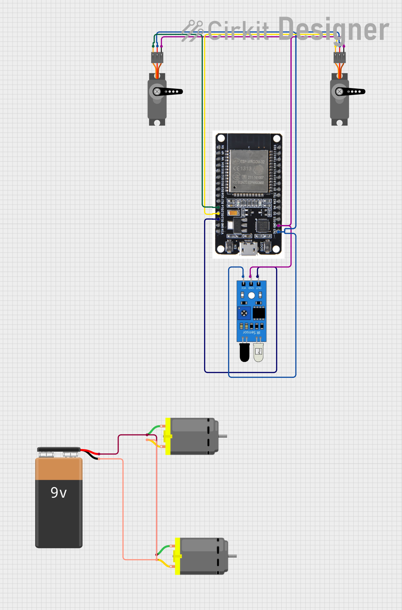
This circuit is designed to interface an ESP32 microcontroller with two servo motors, an infrared (IR) sensor, and two DC motors powered by a 9V battery. The ESP32 is used to control the servo motors and read the output from the IR sensor. The DC motors are connected in parallel to the 9V battery.
Component List
ESP32
- Description: A microcontroller with Wi-Fi and Bluetooth capabilities, featuring a wide range of GPIO pins.
- Pins: EN, VP, VN, D34, D35, D32, D33, D25, D26, D27, D14, D12, D13, GND, VIN, 3V3, D15, D2, D4, RX2, TX2, D5, D18, D19, D21, RX0, TX0, D22, D23, BOOT
IR Sensor
- Description: A sensor that detects infrared light, commonly used for proximity or object detection.
- Pins: out, gnd, vcc
Servo (2x)
- Description: An actuator capable of precise control of angular position, commonly used for steering mechanisms or robotic arms.
- Pins: GND, VCC, PWM
DC Motor (2x)
- Description: An electric motor that runs on direct current (DC) electricity.
- Pins: pin 1, pin 2
9V Battery
- Description: A standard 9V battery used to provide power to the DC motors.
- Pins: -, +
Wiring Details
ESP32
- D14: Connected to the PWM pin of one Servo.
- D12: Connected to the PWM pin of the other Servo.
- D13: Connected to the out pin of the IR Sensor.
- 3V3: Connected to the VCC pins of both Servos and the vcc pin of the IR Sensor.
- GND: Connected to the GND pins of both Servos and the gnd pin of the IR Sensor.
IR Sensor
- out: Connected to the D13 pin of the ESP32.
- gnd: Connected to the GND pin of the ESP32.
- vcc: Connected to the 3V3 pin of the ESP32.
Servo (2x)
- PWM: Each Servo's PWM pin is connected to a separate GPIO pin (D14, D12) on the ESP32 for independent control.
- VCC: Connected to the 3V3 pin of the ESP32.
- GND: Connected to the GND pin of the ESP32.
DC Motor (2x)
- pin 1: Both DC Motors' pin 1 are connected to the + pin of the 9V Battery.
- pin 2: Both DC Motors' pin 2 are connected to the - pin of the 9V Battery.
9V Battery
- +: Connected to pin 1 of both DC Motors.
- -: Connected to pin 2 of both DC Motors.
Documented Code
There is no code provided for the microcontroller. The documentation of the code would typically include a description of the functionality, setup, and main loop, along with any functions or libraries used. Since no code is available, this section cannot be completed. If code becomes available, it should be documented here with comments explaining the purpose and functionality of each section of the code.