Cirkit Designer
Your all-in-one circuit design IDE
Home /
Project Documentation
Arduino UNO-Based Automated Water Control System with Soil Moisture and Rain Sensing

Circuit Documentation
Summary
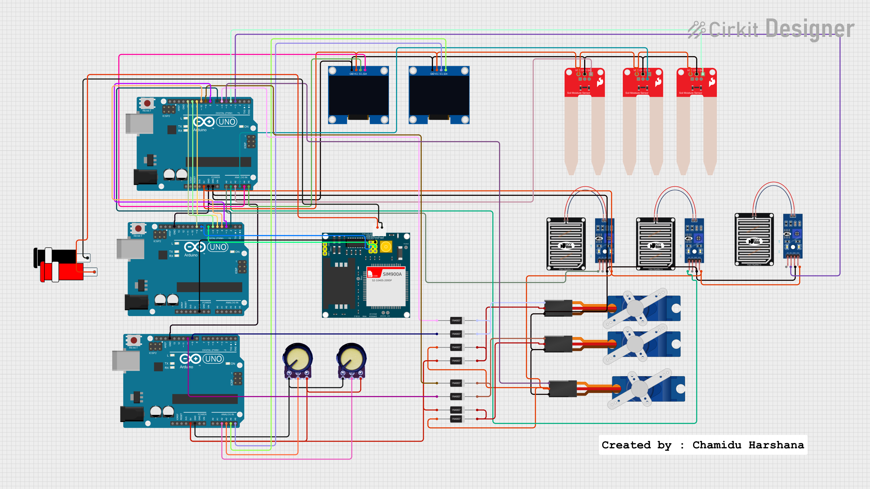
This circuit is designed to monitor soil moisture and rain presence to control a water management system. It uses multiple sensors to detect environmental conditions and servos to actuate doors or valves based on the sensor readings. The system is controlled by three Arduino UNO microcontrollers, which are programmed to read sensor inputs and drive the servos accordingly. The circuit also includes OLED displays for user interface and feedback.
Component List
Microcontrollers
- Arduino UNO: A microcontroller board based on the ATmega328P, equipped with digital input/output pins, analog inputs, a USB connection, a power jack, an ICSP header, and a reset button.
Sensors
- SparkFun Soil Moisture Sensor: Measures the volumetric content of water in soil and gives a moisture level as output.
- RAIN SENSOR: Detects rainwater and provides both analog and digital outputs.
- Potentiometer: A three-terminal resistor with a sliding or rotating contact that forms an adjustable voltage divider.
Actuators
- Tower Pro SG90 servo: A small and lightweight servo motor capable of precise control.
Displays
- 128x64 OLED Display (I2C IIC SPI Serial): A small display for showing text or graphics, interfaced via I2C.
Power
- Connector 5V: Provides a connection point for a 5V power supply.
Protection
- 1N4007 Rectifier Diode: A diode used for protecting components from voltage spikes by allowing current to flow in one direction only.
Wiring Details
Arduino UNO
- Digital Pins
- D2-D13: Various connections to sensors, servos, and other Arduinos for control signals.
- Analog Pins
- A0-A5: Used for reading analog sensor values from soil moisture sensors and potentiometers.
- Power Pins
- 5V: Supplies power to sensors and servos.
- GND: Common ground for the circuit.
SparkFun Soil Moisture Sensor
- VCC: Connected to 5V power.
- GND: Connected to ground.
- SIG: Analog signal output connected to an Arduino analog input pin.
RAIN SENSOR
- VCC: Connected to 5V power.
- GRD: Connected to ground.
- AO: Analog output connected to an Arduino analog input pin.
- DO: Digital output connected to an Arduino digital input pin.
Tower Pro SG90 servo
- Signal: Control signal connected to an Arduino digital output pin.
- +5V: Power supply connected to 5V.
- GND: Connected to ground.
128x64 OLED Display (I2C IIC SPI Serial)
- VCC: Connected to 5V power.
- GND: Connected to ground.
- SDA: I2C data line connected to an Arduino analog input pin configured as SDA.
- SCL: I2C clock line connected to an Arduino analog input pin configured as SCL.
Connector 5V
- VCC: 5V power supply input.
- GND: Connected to ground.
1N4007 Rectifier Diode
- Anode: Connected to an Arduino digital output pin.
- Cathode: Connected to servo signal lines or other diodes to form a diode logic network.
Documented Code
Arduino UNO (Main Controller)
#include <U8g2lib.h>
#include <Servo.h>

const int waterSensor1Pin = A0;
const int soilMoisture1Pin = A1;
const int waterSensor2pin = A2;
const int soilMoisture2pin = A3;
const int waterSensor3pin = 3;
const int soilMoisture3pin = 4;
const int ServoPin1 = 6;
const int ServoPin2 = 9;
const int ServoPin3 = 5;

int waterSensor3Value = 1;
int soilMoisture3Value = 1;

Servo Fservo;
Servo Sservo;
Servo Tservo;

U8G2_SSD1306_128X64_NONAME_F_HW_I2C u8g2(U8G2_R0, /* reset=*/U8X8_PIN_NONE);
int R1limite = 800;
int R2limite = 175;
int S1limite = 450;
int S2limite = 450;

void setup() {
  Fservo.attach(ServoPin1);
  Sservo.attach(ServoPin2);
  Tservo.attach(ServoPin3);

  pinMode(3, INPUT);
  pinMode(4, INPUT);

  pinMode(7, OUTPUT);
  pinMode(8, OUTPUT);
  pinMode(10, OUTPUT);
  pinMode(11, OUTPUT);
  pinMode(12, OUTPUT);
  pinMode(13, OUTPUT);

  u8g2.begin();

  u8g2.setFont(u8g2_font_ncenB08_tr);
  u8g2.drawStr(17, 10, "Water Controll");
  u8g2.sendBuffer();
  u8g2.setFont(u8g2_font_ncenB08_tr);
  u8g2.drawStr(0, 20, "Automation System");
  u8g2.sendBuffer();
  u8g2.setFont(u8g2_font_ncenB08_tr);
  u8g2.drawStr(30, 40, "Made By");
  u8g2.sendBuffer();
  u8g2.setFont(u8g2_font_ncenB08_tr);
  u8g2.drawStr(0, 60, "CHAMIDU HARSHANA");
  u8g2.sendBuffer();

  delay(4000);

  u8g2.clearBuffer();
  u8g2.drawStr(37, 20, "System");
  u8g2.sendBuffer();

  u8g2.setFont(u8g2_font_ncenB08_tr);
  u8g2.drawStr(20, 40, "Auto Mode On");
  u8g2.sendBuffer();

  delay(3000);
}

void loop() {
  int waterSensor1Value = analogRead(waterSensor1Pin);
  int soilMoisture1Value = analogRead(soilMoisture1Pin);
  int waterSensor2Value = analogRead(waterSensor2pin);
  int soilMoisture2Value = analogRead(soilMoisture2pin);
  waterSensor3Value = digitalRead(waterSensor3pin);
  soilMoisture3Value = digitalRead(soilMoisture3pin);

  u8g2.clearBuffer();

  // Various conditions to control servos and display messages based on sensor readings
  // ...

  u8g2.sendBuffer();
  delay(100);
}
Arduino UNO (Secondary Controllers)
void setup() {
  // Secondary controllers may have additional setup code here.
}

void loop() {
  // Secondary controllers may have additional loop code here.
}
Note: The secondary Arduino UNOs are not provided with specific code in the input. They are likely intended to be programmed with similar or complementary logic to the main controller.