Cirkit Designer
Your all-in-one circuit design IDE
Home /
Project Documentation
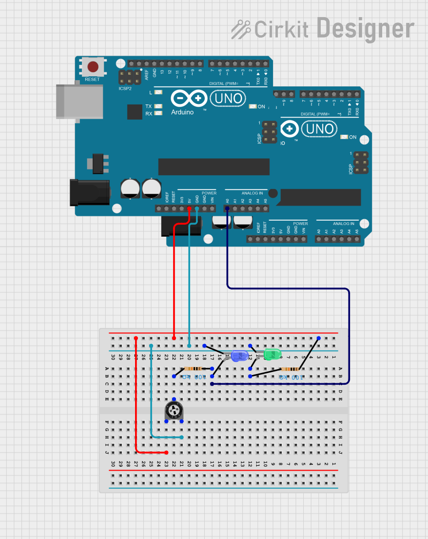
Dual Arduino UNO LED Control with Adjustable Brightness
Circuit Documentation
Summary
This circuit involves two Arduino UNO microcontrollers, two LEDs (one green and one blue), two resistors, and a trimmer potentiometer. The circuit is designed to control the LEDs using the Arduino microcontrollers, with the trimmer potentiometer providing adjustable resistance.
Component List
Arduino UNO
- Description: A microcontroller board based on the ATmega328P.
- Pins: UNUSED, IOREF, Reset, 3.3V, 5V, GND, Vin, A0, A1, A2, A3, A4, A5, SCL, SDA, AREF, D13, D12, D11, D10, D9, D8, D7, D6, D5, D4, D3, D2, D1, D0
LED: Two Pin (green)
- Description: A green LED with two pins: cathode and anode.
- Pins: cathode, anode
LED: Two Pin (blue)
- Description: A blue LED with two pins: cathode and anode.
- Pins: cathode, anode
Resistor
- Description: A resistor with a resistance of 100,000 Ohms.
- Pins: pin1, pin2
- Properties: Resistance: 100,000 Ohms
Resistor
- Description: A resistor with a resistance of 100,000 Ohms.
- Pins: pin1, pin2
- Properties: Resistance: 100,000 Ohms
Trimmer Potentiometer
- Description: A trimmer potentiometer with a resistance of 10,000 Ohms.
- Pins: leg1, wiper, leg2
- Properties: Resistance: 10,000 Ohms
Wiring Details
Arduino UNO
5V Pin:
- Connected to pin1 of a resistor
- Connected to leg1 of the trimmer potentiometer
GND Pin:
- Connected to the cathode of the green LED
- Connected to the cathode of the blue LED
- Connected to leg2 of the trimmer potentiometer
A0 Pin:
- Connected to pin1 of a resistor
- Connected to the anode of the blue LED
LED: Two Pin (green)
Cathode:
- Connected to GND of Arduino UNO
Anode:
- Connected to pin2 of a resistor
LED: Two Pin (blue)
Cathode:
- Connected to GND of Arduino UNO
Anode:
- Connected to pin1 of a resistor
Resistor
Pin1:
- Connected to 5V of Arduino UNO
- Connected to leg1 of the trimmer potentiometer
Pin2:
- Connected to the anode of the green LED
Resistor
Pin1:
- Connected to A0 of Arduino UNO
- Connected to the anode of the blue LED
Pin2:
- Connected to the wiper of the trimmer potentiometer
Trimmer Potentiometer
Leg1:
- Connected to 5V of Arduino UNO
- Connected to pin1 of a resistor
Wiper:
- Connected to pin2 of a resistor
Leg2:
- Connected to GND of Arduino UNO
Documented Code
Arduino UNO (Instance 1)
File Name: sketch.ino
void setup() {
  // put your setup code here, to run once:

}

void loop() {
  // put your main code here, to run repeatedly:

}
File Name: documentation.txt
Arduino UNO (Instance 2)
File Name: sketch.ino
void setup() {
  // put your setup code here, to run once:

}

void loop() {
  // put your main code here, to run repeatedly:

}
File Name: documentation.txt