
Wi-Fi Controlled ESP32 Smart Lock with 12V Solenoid and Relay
View and Edit Project In Cirkit Designer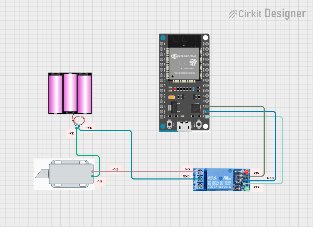
Circuit Documentation
Summary
This circuit is designed to control a 12V solenoid lock using an ESP32 Devkit V1 microcontroller and a 1 Channel Relay 5V. The ESP32 connects to a Wi-Fi network and hosts a web server that allows remote control of the solenoid lock. The relay acts as an intermediary to switch the high voltage required by the solenoid lock.
Component List
12V Solenoid Lock
- Description: An electromechanical lock that operates on 12V.
- Pins:
+,- - Purpose: To lock and unlock a door.
ESP32 Devkit V1
- Description: A microcontroller with Wi-Fi and Bluetooth capabilities.
- Pins:
3V3,GND,D15,D2,D4,RX2,TX2,D5,D18,D19,D21,RX0,TX0,D22,D23,EN,VP,VN,D34,D35,D32,D33,D25,D26,D27,D14,D12,D13,VIN - Purpose: To control the relay and host the web server for remote control.
Battery 12V
- Description: A 12V power source.
- Pins:
+,- - Purpose: To provide power to the solenoid lock.
1 Channel Relay 5V
- Description: A relay module that operates on 5V and can switch higher voltages.
- Pins:
VCC,GND,IN,NC,COM,NO - Purpose: To switch the 12V power to the solenoid lock based on the control signal from the ESP32.
Wiring Details
12V Solenoid Lock
- Pin
-is connected to Pin-of the Battery 12V. - Pin
+is connected to PinNCof the 1 Channel Relay 5V.
ESP32 Devkit V1
- Pin
3V3is connected to PinVCCof the 1 Channel Relay 5V. - Pin
GNDis connected to PinGNDof the 1 Channel Relay 5V. - Pin
D15is connected to PinINof the 1 Channel Relay 5V.
Battery 12V
- Pin
+is connected to PinCOMof the 1 Channel Relay 5V. - Pin
-is connected to Pin-of the 12V Solenoid Lock.
1 Channel Relay 5V
- Pin
VCCis connected to Pin3V3of the ESP32 Devkit V1. - Pin
GNDis connected to PinGNDof the ESP32 Devkit V1. - Pin
INis connected to PinD15of the ESP32 Devkit V1. - Pin
NCis connected to Pin+of the 12V Solenoid Lock. - Pin
COMis connected to Pin+of the Battery 12V.
Code Documentation
Code for ESP32 Devkit V1
#include <WiFi.h>
#include <WebServer.h>

const char* ssid = "your_SSID";
const char* password = "your_PASSWORD";

WebServer server(80);

// Define GPIO pin for the relay
const int relayPin = 15;

void setup() {
  Serial.begin(115200);
  pinMode(relayPin, OUTPUT);
  digitalWrite(relayPin, HIGH);  // Lock is initially locked

  // Connect to Wi-Fi
  WiFi.begin(ssid, password);
  while (WiFi.status() != WL_CONNECTED) {
    delay(1000);
    Serial.println("Connecting to WiFi...");
  }

  Serial.println("Connected to WiFi");

  // Setup server routes
  server.on("/unlock", handleUnlock);
  server.begin();
  Serial.println("HTTP server started");
}

void handleUnlock() {
  digitalWrite(relayPin, LOW);  // Unlock the door
  delay(5000);  // Keep it unlocked for 5 seconds
  digitalWrite(relayPin, HIGH); // Lock again
  server.send(200, "text/plain", "Door unlocked");
}

void loop() {
  server.handleClient();
}
Code Explanation
- Libraries: The code includes the
WiFi.handWebServer.hlibraries for Wi-Fi connectivity and web server functionality. - Wi-Fi Credentials: The SSID and password for the Wi-Fi network are defined.
- Web Server: A web server is created on port 80.
- Relay Pin: The GPIO pin for the relay is defined as
relayPinand set to pin 15. - Setup Function:
- Initializes serial communication.
- Sets the relay pin as an output and initially sets it to HIGH (locked state).
- Connects to the Wi-Fi network and waits until the connection is established.
- Sets up the web server route for unlocking the door.
- Handle Unlock Function: This function is called when the
/unlockroute is accessed. It unlocks the door for 5 seconds and then locks it again. - Loop Function: Continuously handles incoming client requests to the web server.