Arduino Nano-Powered PID Line Following Robot with Reflectance Sensor Array and Dual Motor Driver
Circuit Documentation
Summary
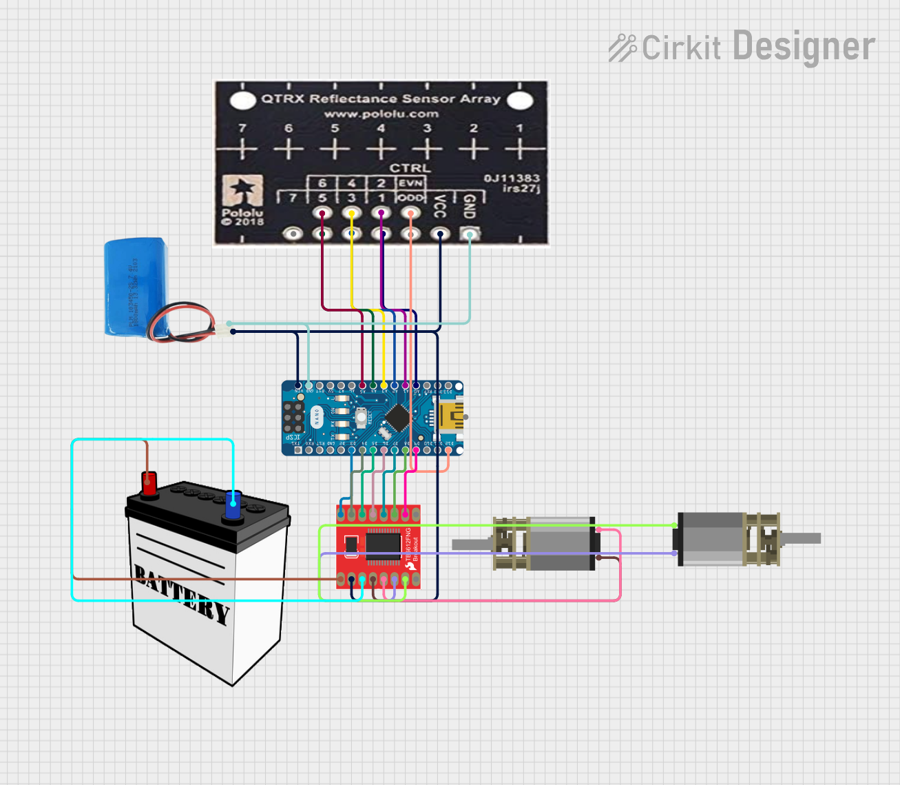
This circuit is designed for an advanced line-following robot that uses a PID control algorithm for precise movement. The core components include a QTRX-HD-07RC Reflectance Sensor Array for line sensing, a Motor Driver 1A Dual TB6612FNG for controlling two DC Mini Metal Gear Motors, and an Arduino Nano microcontroller for processing the sensor data and controlling the motors. The circuit is powered by a 5V battery for the logic and a 12V battery for the motor power.
Component List
QTRX-HD-07RC Reflectance Sensor Array
- Description: A sensor array used to detect the presence and position of a line on the surface.
- Pins: GND, VCC, EVN, ODD, 1, 2, 3, 4, 5, 6, 7
Motor Driver 1A Dual TB6612FNG
- Description: A motor driver capable of driving two DC motors.
- Pins: GND, B01, B02, A02, A01, VCC, VM, PWMA, AIN2, AIN1, STBY, BIN1, BIN2, PWMB
Arduino Nano
- Description: A compact microcontroller board based on the ATmega328P.
- Pins: D1/TX, D0/RX, RESET, GND, D2, D3, D4, D5, D6, D7, D8, D9, D10, D11/MOSI, D12/MISO, VIN, 5V, A7, A6, A5, A4, A3, A2, A1, A0, AREF, 3V3, D13/SCK
5V Battery
- Description: Provides power to the logic components of the circuit.
- Pins: positive, negative
DC Mini Metal Gear Motor (x2)
- Description: Small DC motors with gear reduction for driving the robot's wheels.
- Pins: IN1, IN2
12V Battery
- Description: Provides power to the motor driver for driving the motors.
- Pins: VCC, GND
Wiring Details
QTRX-HD-07RC Reflectance Sensor Array
- GND connected to 5V battery negative
- VCC connected to 5V battery positive
- EVN connected to Arduino Nano D12/MISO
- Pins 1 to 6 connected to Arduino Nano A0 to A5 respectively
Motor Driver 1A Dual TB6612FNG
- GND connected to 12V battery GND
- VCC connected to 5V battery positive
- VM connected to 12V battery VCC
- PWMA connected to Arduino Nano D3
- AIN2 connected to Arduino Nano D4
- AIN1 connected to Arduino Nano D5
- STBY connected to Arduino Nano D6
- BIN1 connected to Arduino Nano D7
- BIN2 connected to Arduino Nano D8
- PWMB connected to Arduino Nano D9
- B01 connected to DC Mini Metal Gear Motor IN1 (Motor 2)
- B02 connected to DC Mini Metal Gear Motor IN2 (Motor 2)
- A01 connected to DC Mini Metal Gear Motor IN1 (Motor 1)
- A02 connected to DC Mini Metal Gear Motor IN2 (Motor 1)
Arduino Nano
- GND connected to 5V battery negative
- VIN connected to 5V battery positive
- Digital and Analog pins connected as per the above details
DC Mini Metal Gear Motors
- Motor 1 IN1 and IN2 connected to Motor Driver A01 and A02
- Motor 2 IN1 and IN2 connected to Motor Driver B01 and B02
5V Battery
- Positive connected to Arduino Nano VIN, Motor Driver VCC, and Reflectance Sensor Array VCC
- Negative connected to Arduino Nano GND and Reflectance Sensor Array GND
12V Battery
- VCC connected to Motor Driver VM
- GND connected to Motor Driver GND
Documented Code
/*
 * Arduino Sketch for advanced line following using PID control
 *
 * Components:
 * - QTRX-HD-07RC Reflectance Sensor Array
 * - Motor Driver 1A Dual TB6612FNG
 * - Two DC Mini Metal Gear Motors
 * - Arduino Nano
 *
 * Connections:
 * - Reflectance Sensor Array to Arduino Analog Pins A0-A5
 * - Motor Driver to Arduino Digital Pins D3-D9
 * - Power connections as per the provided net list
 */

// Pin definitions
const int sensorPins[] = {A0, A1, A2, A3, A4, A5};
const int motorPWMA = 3;
const int motorAIN2 = 4;
const int motorAIN1 = 5;
const int motorSTBY = 6;
const int motorBIN1 = 7;
const int motorBIN2 = 8;
const int motorPWMB = 9;

// PID control variables
float Kp = 0.5;
float Ki = 0.0;
float Kd = 0.1;
float lastError = 0;
float integral = 0;

void setup() {
  // Initialize sensor pins
  for (int i = 0; i < 6; i++) {
    pinMode(sensorPins[i], INPUT);
  }
  // Initialize motor driver pins
  pinMode(motorPWMA, OUTPUT);
  pinMode(motorAIN2, OUTPUT);
  pinMode(motorAIN1, OUTPUT);
  pinMode(motorSTBY, OUTPUT);
  pinMode(motorBIN1, OUTPUT);
  pinMode(motorBIN2, OUTPUT);
  pinMode(motorPWMB, OUTPUT);
  // Enable motor driver
  digitalWrite(motorSTBY, HIGH);
}

void loop() {
  // Read sensor values
  int sensorValues[6];
  for (int i = 0; i < 6; i++) {
    sensorValues[i] = analogRead(sensorPins[i]);
  }
  // Calculate error
  int error = (sensorValues[0] * -2 + sensorValues[1] * -1 + sensorValues[2] * 0 +
               sensorValues[3] * 0 + sensorValues[4] * 1 + sensorValues[5] * 2);
  // PID calculations
  integral += error;
  float derivative = error - lastError;
  float output = Kp * error + Ki * integral + Kd * derivative;
  lastError = error;
  // Calculate motor speeds
  int baseSpeed = 150;
  int leftMotorSpeed = baseSpeed + output;
  int rightMotorSpeed = baseSpeed - output;
  leftMotorSpeed = constrain(leftMotorSpeed, 0, 255);
  rightMotorSpeed = constrain(rightMotorSpeed, 0, 255);
  // Set motor speeds
  analogWrite(motorPWMA, leftMotorSpeed);
  analogWrite(motorPWMB, rightMotorSpeed);
  // Set motor directions
  digitalWrite(motorAIN1, leftMotorSpeed > 127 ? HIGH : LOW);
  digitalWrite(motorAIN2, leftMotorSpeed > 127 ? LOW : HIGH);
  digitalWrite(motorBIN1, rightMotorSpeed > 127 ? HIGH : LOW);
  digitalWrite(motorBIN2, rightMotorSpeed > 127 ? LOW : HIGH);
  delay(10);
}
This code is responsible for reading the sensor values from the QTRX-HD-07RC Reflectance Sensor Array, calculating the error for the PID control, and adjusting the speed and direction of the DC Mini Metal Gear Motors accordingly. The PID control parameters (Kp, Ki, Kd) can be tuned to optimize the robot's line-following performance.