Cirkit Designer
Your all-in-one circuit design IDE
Home /
Project Documentation
Arduino UNO Blinking LED Circuit
Circuit Documentation
Summary of the Circuit
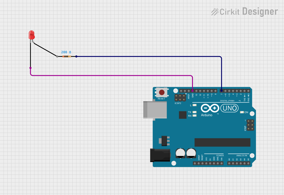
This circuit is designed to control a red two-pin LED using an Arduino UNO microcontroller. The LED is connected to one of the digital pins (D7) of the Arduino through a 200 Ohm resistor. The purpose of the resistor is to limit the current flowing through the LED to prevent it from burning out. The LED is turned on and off with a 1-second interval, which is controlled by the embedded code running on the Arduino UNO.
Component List
Arduino UNO
- Description: A microcontroller board based on the ATmega328P.
- Pins Used: GND, D7
- Purpose: Acts as the control unit for the LED, providing the necessary logic and power signals.
LED: Two Pin (red)
- Description: A basic red light-emitting diode.
- Pins: cathode, anode
- Purpose: Emits light when powered.
Resistor
- Description: A passive two-terminal electrical component that implements electrical resistance as a circuit element.
- Value: 200 Ohms
- Purpose: Limits the current flowing through the LED to prevent damage.
Wiring Details
Arduino UNO
- GND is connected to the cathode of the LED.
- D7 is connected to one end of the Resistor (pin2).
LED: Two Pin (red)
- Cathode is connected to the GND of the Arduino UNO.
- Anode is not directly connected in the provided net list, but it is implied that it connects to the other end of the Resistor (pin1).
Resistor
- Pin1 is assumed to be connected to the anode of the LED.
- Pin2 is connected to the D7 pin of the Arduino UNO.
Documented Code
/*
 * This Arduino Sketch controls an LED connected to pin D7 of the Arduino UNO.
 * The LED will be turned on for 1 second and then turned off for 1 second
 * repeatedly.
 */

void setup() {
  // Initialize digital pin D7 as an output.
  pinMode(7, OUTPUT);
}

void loop() {
  // Turn the LED on (HIGH is the voltage level)
  digitalWrite(7, HIGH);
  // Wait for a second
  delay(1000);
  // Turn the LED off by making the voltage LOW
  digitalWrite(7, LOW);
  // Wait for a second
  delay(1000);
}
- File Name: sketch.ino
- Description: The code configures pin D7 as an output and then toggles it between HIGH and LOW states with a delay of 1 second between each state change. This blinking pattern creates a visual indication that the microcontroller is functioning and controlling the LED.