
ESP8266-Based Air Quality Monitoring System with LCD Display and Wi-Fi Connectivity
View and Edit Project In Cirkit Designer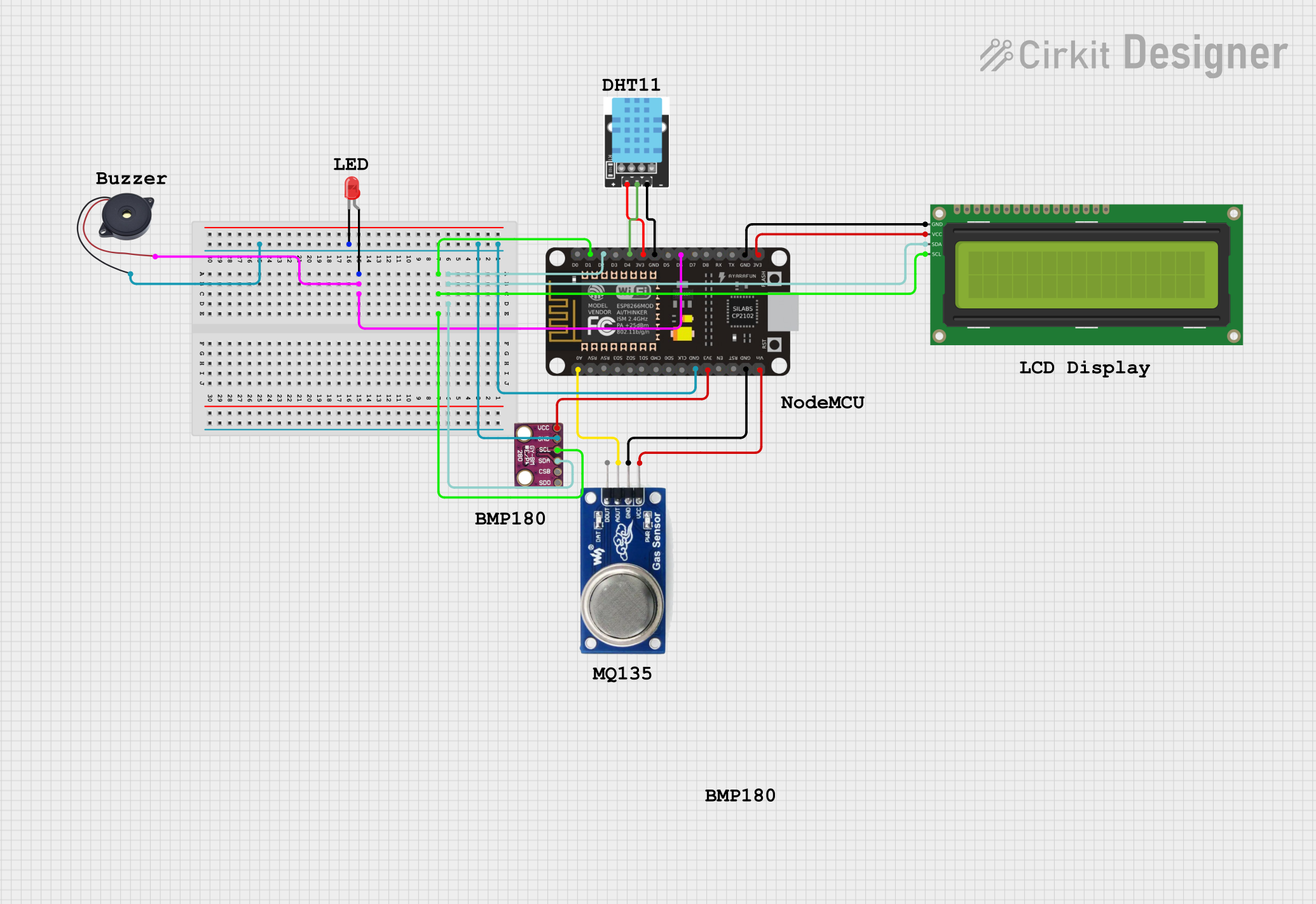
Air Quality Monitoring System Documentation
Summary
This document provides a detailed overview of the Air Quality Monitoring System circuit. The system utilizes an ESP8266 NodeMCU microcontroller to interface with various sensors and output devices, including an LCD display, a buzzer, and multiple environmental sensors. The system monitors air quality, temperature, humidity, and pressure, and displays the data on an LCD screen. It also sends the data to a Blynk server for remote monitoring and triggers a buzzer if certain thresholds are exceeded.
Component List
LED: Two Pin (red)
- Pins: Cathode, Anode
- Description: A red LED used for visual indication.
16x2 I2C LCD
- Pins: GND, VCC, SDA, SCL
- Description: A 16x2 character LCD with I2C interface for displaying sensor data.
Buzzer
- Pins: GND, IN
- Description: An active buzzer used for audible alerts.
MQ 135
- Pins: D OUT, A OUT, GND, VCC
- Description: An air quality sensor for detecting various gases.
ESP8266 NodeMCU
- Pins: D0, D1, D2, D3, D4, 3V3, GND, D5, D6, D7, D8, RX, TX, A0, RSV, SD3, SD2, SD1, CMD, SD0, CLK, EN, RST, VIN
- Description: A Wi-Fi enabled microcontroller used as the main processing unit.
BMP280
- Pins: SDO, CSB, SDA, SCL, GND, VCC
- Description: A barometric pressure sensor with I2C interface.
KY-015 DHT11 Temperature-Humidity Sensor Module
- Pins: VCC, GND, DOUT
- Description: A sensor module for measuring temperature and humidity.
Wiring Details
LED: Two Pin (red)
- Anode: Connected to D6 on ESP8266 NodeMCU
- Cathode: Connected to GND on ESP8266 NodeMCU
16x2 I2C LCD
- GND: Connected to GND on ESP8266 NodeMCU
- VCC: Connected to 3V3 on ESP8266 NodeMCU
- SDA: Connected to D2 on ESP8266 NodeMCU
- SCL: Connected to D1 on ESP8266 NodeMCU
Buzzer
- GND: Connected to GND on ESP8266 NodeMCU
- IN: Connected to D6 on ESP8266 NodeMCU
MQ 135
- A OUT: Connected to A0 on ESP8266 NodeMCU
- GND: Connected to GND on ESP8266 NodeMCU
- VCC: Connected to VIN on ESP8266 NodeMCU
ESP8266 NodeMCU
- D2: Connected to SDA on 16x2 I2C LCD and BMP280
- D1: Connected to SCL on 16x2 I2C LCD and BMP280
- D6: Connected to Anode of LED and IN of Buzzer
- GND: Connected to Cathode of LED, GND of Buzzer, GND of BMP280, GND of 16x2 I2C LCD, GND of MQ 135, and GND of KY-015 DHT11
- 3V3: Connected to VCC of 16x2 I2C LCD, VCC of BMP280, and VCC of KY-015 DHT11
- VIN: Connected to VCC of MQ 135
- A0: Connected to A OUT of MQ 135
- D4: Connected to DOUT of KY-015 DHT11
BMP280
- SDA: Connected to D2 on ESP8266 NodeMCU
- SCL: Connected to D1 on ESP8266 NodeMCU
- GND: Connected to GND on ESP8266 NodeMCU
- VCC: Connected to 3V3 on ESP8266 NodeMCU
KY-015 DHT11 Temperature-Humidity Sensor Module
- VCC: Connected to 3V3 on ESP8266 NodeMCU
- GND: Connected to GND on ESP8266 NodeMCU
- DOUT: Connected to D4 on ESP8266 NodeMCU
Code Documentation
#define BLYNK_TEMPLATE_ID "TMPL3ljJ3Anak"
#define BLYNK_TEMPLATE_NAME "Air Quality Montoring System"
#define BLYNK_AUTH_TOKEN "bhqwFBHQez9JeTN8mEHTZhLkci9Dwdo2"

#include <Wire.h>
#include <LiquidCrystal_I2C.h>
#include <Adafruit_Sensor.h>
#include <Adafruit_BMP280.h>
#include <DHT.h>
#include <ESP8266WiFi.h>
#include <BlynkSimpleEsp8266.h>

// Pin Definitions
#define DHTPIN D4
#define DHTTYPE DHT11
#define MQ135_PIN A0
#define BUZZER_PIN D6

// Objects Initialization
DHT dht(DHTPIN, DHTTYPE);
Adafruit_BMP280 bmp; // Default I2C address 0x76
LiquidCrystal_I2C lcd(0x27, 16, 2);

// WiFi credentials
char auth[] = BLYNK_AUTH_TOKEN;
char ssid[] = "Arjit Mittal";
char pass[] = "Arjit@3005";

// Blynk Timer
BlynkTimer timer;

void setup() {
  // Serial Monitor
  Serial.begin(115200);

  // Initialize Blynk
  Blynk.begin(auth, ssid, pass);

  // Initialize DHT11
  dht.begin();

  // Initialize LCD
  lcd.init();
  lcd.backlight();

  // Display startup message
  lcd.setCursor(0, 0);
  lcd.print("GROUP 4");
  lcd.setCursor(0, 1);
  lcd.print("AIR MONITORING");
  delay(2000);

  // Set Buzzer pin
  pinMode(12, OUTPUT);

  // Initialize BMP280
  if (!bmp.begin(0x76)) {
    Serial.println("Could not find BMP280 sensor!");
    while (1);
  }

  // Timer to read sensors and update Blynk
  timer.setInterval(2000L, readSensors);
}

void readSensors() {
  // Read DHT11 data
  float temperatureDHT = dht.readTemperature();
  float humidity = dht.readHumidity();

  // Read BMP280 data
  float pressure = bmp.readPressure() / 100.0F; // Convert to hPa
  float altitude = bmp.readAltitude(1013.25); // Standard sea level pressure

  // Read MQ135 data
  int airQuality = analogRead(MQ135_PIN);

  // Display data on LCD
  lcd.clear();
  lcd.setCursor(0, 0);
  lcd.print("Temp: ");
  lcd.print(temperatureDHT);
  lcd.print("C");
  lcd.setCursor(0, 1);
  lcd.print("Hum: ");
  lcd.print(humidity);
  lcd.print("%");

  delay(5000);

  lcd.clear();
  lcd.setCursor(0, 0);
  lcd.print("Air Quality: ");
  lcd.print(airQuality);
  lcd.setCursor(0, 1);
  lcd.print("Pressure: ");
  lcd.print(pressure);
  lcd.print("hPa");

  delay(4000);

  lcd.clear();
  lcd.setCursor(0, 0);
  lcd.print("Altitude: ");
  lcd.print(altitude);

  delay(3000);

  // Push data to Blynk
  Blynk.virtualWrite(V0, temperatureDHT);
  Blynk.virtualWrite(V1, humidity);
  Blynk.virtualWrite(V2, airQuality);
  Blynk.virtualWrite(V3, pressure);
  Blynk.virtualWrite(V4, altitude);

  // Trigger buzzer if air quality exceeds threshold
  if (airQuality > 350 || temperatureDHT > 30) {
    digitalWrite(12, HIGH);
    // Blynk.email("prakharg.1981@gmail.com", "Alert", "Temperature over 28C!");
    Blynk.logEvent("pollution_alert","High Air Quality Detected!");
  } else {
    digitalWrite(12, LOW);
  }
}

void loop() {
  Blynk.run();
  timer.run();
}
This documentation provides a comprehensive overview of the Air Quality Monitoring System, including the components used, their wiring details, and the code running on the ESP8266 NodeMCU.