
Arduino UNO-Based Battery-Powered Piezo Sensor System with LCD Display
View and Edit Project In Cirkit Designer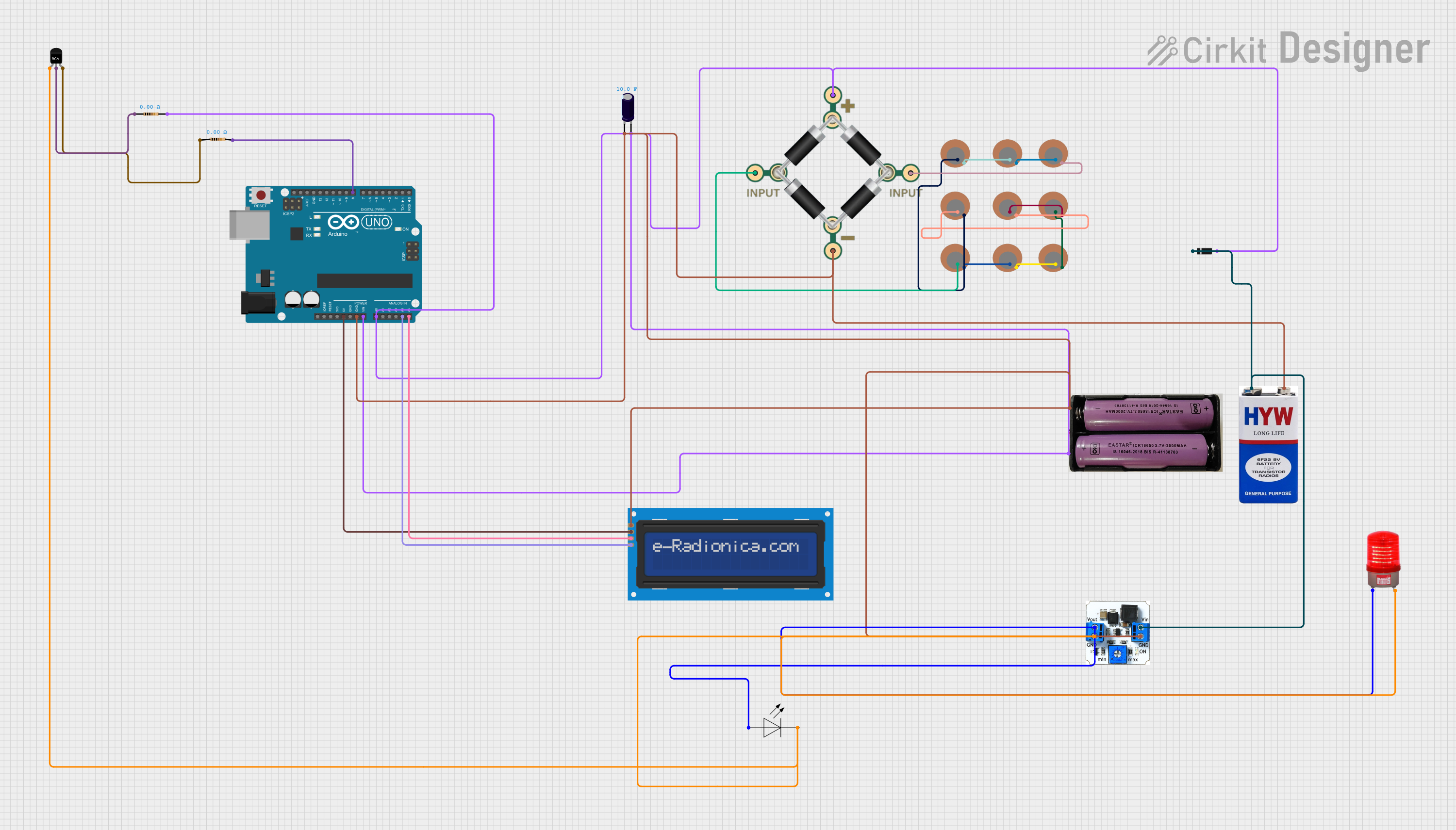
Circuit Documentation
Summary
This circuit involves an Arduino UNO microcontroller interfacing with various components including a 16x2 I2C LCD screen, multiple piezo sensors, a DC/DC booster, a bridge rectifier, an electrolytic capacitor, resistors, an NPN transistor, a diode, a 9V battery, a 7.4V power source, and LED lights. The circuit is designed to read inputs from piezo sensors, display information on the LCD screen, and control LED lights.
Component List
Arduino UNO
- Description: Microcontroller board based on the ATmega328P.
- Pins: UNUSED, IOREF, Reset, 3.3V, 5V, GND, Vin, A0, A1, A2, A3, A4, A5, SCL, SDA, AREF, D13, D12, D11, D10, D9, D8, D7, D6, D5, D4, D3, D2, D1, D0
Piezo Sensor
- Description: Sensor that generates a voltage when deformed.
- Pins: +, -
DC/DC Booster
- Description: Boosts DC voltage to a higher level.
- Pins: GND, Vin, Vout
BRIDGE - 1N4007
- Description: Bridge rectifier for converting AC to DC.
- Pins: 1 INPUT, 2 INPUT, + PIN, - PIN
Electrolytic Capacitor
- Description: Stores electrical energy.
- Pins: -, +
- Properties: Capacitance: 10 Farads
LCD screen 16x2 I2C
- Description: 16x2 character LCD display with I2C interface.
- Pins: SCL, SDA, VCC, GND
7.4V Power Source
- Description: Provides 7.4V DC power.
- Pins: +, -
Resistor
- Description: Limits current flow.
- Pins: pin1, pin2
- Properties: Resistance: 0 Ohms
NPN-Transistor
- Description: General-purpose NPN transistor.
- Pins: E, C, B
LED Light
- Description: Light-emitting diode.
- Pins: +, -
Red Light 220VAC
- Description: Red indicator light for 220V AC.
- Pins: -, +
Diode
- Description: Allows current to flow in one direction.
- Pins: cathode, anode
9V Battery
- Description: Provides 9V DC power.
- Pins: +, -
Wiring Details
Arduino UNO
- 5V connected to VCC of LCD screen 16x2 I2C.
- GND connected to:
- GND of LCD screen 16x2 I2C
- - of 9V battery
- - of 7.4V power source
- - of Electrolytic Capacitor
- - PIN of BRIDGE - 1N4007
- GND of DC/DC booster
- Vin connected to:
- anode of Diode
- pin2 of Resistor
- A0 of Arduino UNO
- + of 7.4V power source
- + of Electrolytic Capacitor
- + PIN of BRIDGE - 1N4007
- A4 connected to SCL of LCD screen 16x2 I2C.
- A5 connected to SDA of LCD screen 16x2 I2C.
- D8 connected to pin2 of Resistor.
Piezo Sensors
- - of one sensor connected to + of another sensor in a chain.
- + of the last sensor in the chain connected to 1 INPUT of BRIDGE - 1N4007.
- - of the last sensor in the chain connected to 2 INPUT of BRIDGE - 1N4007.
DC/DC Booster
- GND connected to:
- GND of Arduino UNO
- - of 9V battery
- - of 7.4V power source
- - of Electrolytic Capacitor
- - PIN of BRIDGE - 1N4007
- Vin connected to:
- cathode of Diode
- + of 9V battery
- Vout connected to:
- + of LED light
- + of Red light 220VAC
BRIDGE - 1N4007
- 1 INPUT connected to + of Piezo Sensor.
- 2 INPUT connected to - of Piezo Sensor.
- + PIN connected to:
- Vin of Arduino UNO
- A0 of Arduino UNO
- + of 7.4V power source
- + of Electrolytic Capacitor
Electrolytic Capacitor
- - connected to:
- GND of Arduino UNO
- - of 9V battery
- - of 7.4V power source
- - PIN of BRIDGE - 1N4007
- GND of DC/DC booster
- + connected to:
- Vin of Arduino UNO
- A0 of Arduino UNO
- + of 7.4V power source
- + PIN of BRIDGE - 1N4007
LCD screen 16x2 I2C
- VCC connected to 5V of Arduino UNO.
- GND connected to GND of Arduino UNO.
- SCL connected to A4 of Arduino UNO.
- SDA connected to A5 of Arduino UNO.
7.4V Power Source
- + connected to:
- Vin of Arduino UNO
- A0 of Arduino UNO
- + of Electrolytic Capacitor
- + PIN of BRIDGE - 1N4007
- - connected to:
- GND of Arduino UNO
- - of 9V battery
- - of Electrolytic Capacitor
- - PIN of BRIDGE - 1N4007
- GND of DC/DC booster
Resistor
- pin1 connected to C of NPN-Transistor.
- pin2 connected to:
- Vin of Arduino UNO
- anode of Diode
- A0 of Arduino UNO
- + of 7.4V power source
- + of Electrolytic Capacitor
- + PIN of BRIDGE - 1N4007
NPN-Transistor
- E connected to:
- - of LED light
- - of Red light 220VAC
- GND of DC/DC booster
- C connected to pin1 of Resistor.
- B connected to pin1 of another Resistor.
LED Light
- + connected to Vout of DC/DC booster.
- - connected to E of NPN-Transistor.
Red Light 220VAC
- + connected to Vout of DC/DC booster.
- - connected to E of NPN-Transistor.
Diode
- cathode connected to + of 9V battery.
- anode connected to:
- Vin of Arduino UNO
- pin2 of Resistor
- A0 of Arduino UNO
- + of 7.4V power source
- + of Electrolytic Capacitor
- + PIN of BRIDGE - 1N4007
9V Battery
- + connected to:
- cathode of Diode
- Vin of DC/DC booster
- - connected to:
- GND of Arduino UNO
- GND of LCD screen 16x2 I2C
- - of 7.4V power source
- - of Electrolytic Capacitor
- - PIN of BRIDGE - 1N4007
- GND of DC/DC booster