
Arduino and ESP32 Controlled Pneumatic Solenoid Valve with Relay and Voltmeter
View and Edit Project In Cirkit Designer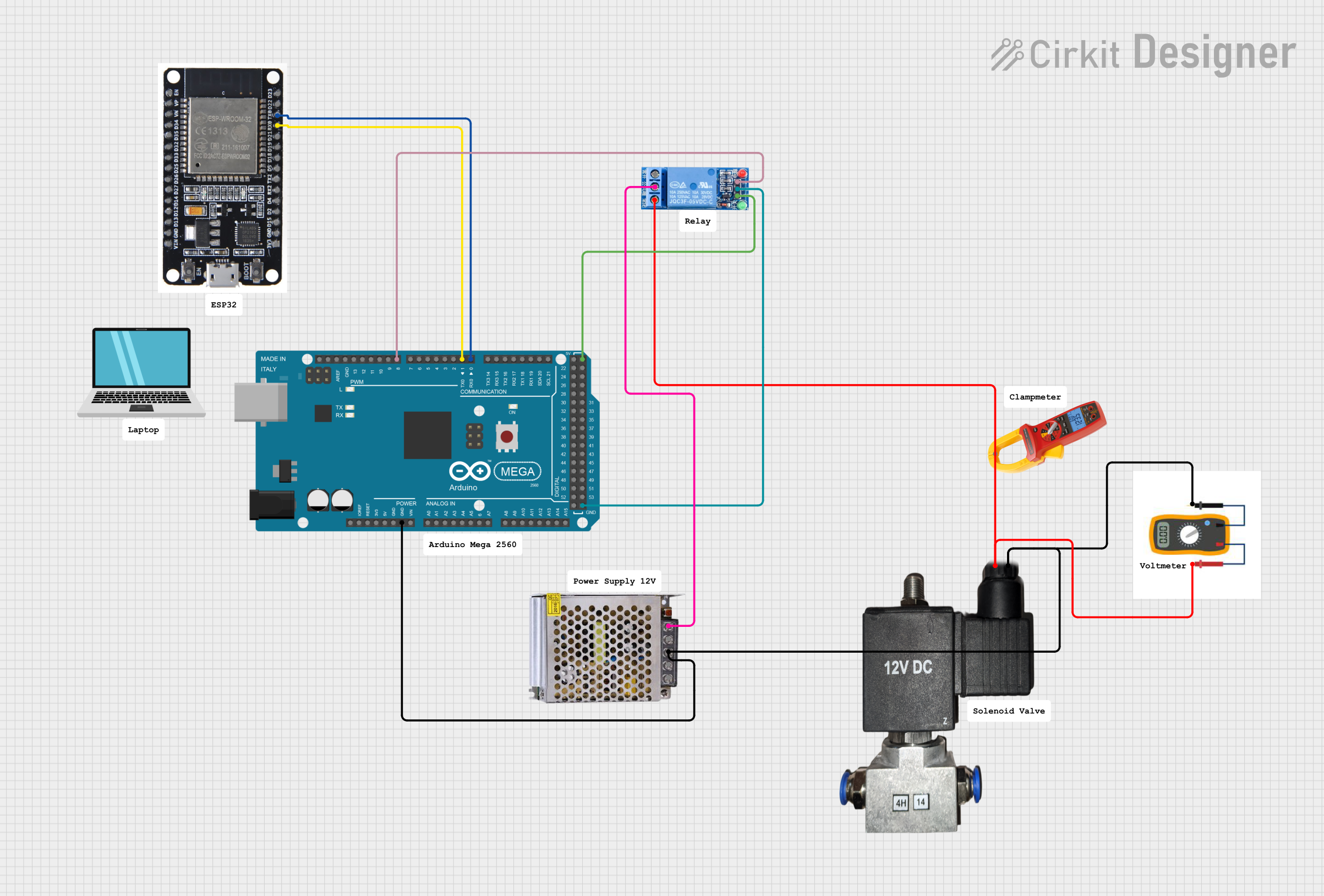
Circuit Documentation
Summary
This circuit involves an Arduino Mega 2560, an ESP32, a 1 Channel Relay, a 12V Pneumatic Solenoid Valve, a 12V 5A Power Supply, and a Voltmeter. The Arduino Mega 2560 is the central microcontroller, interfacing with the ESP32 for communication, controlling the relay, and monitoring the solenoid valve. The power supply provides the necessary voltage for the components, and the voltmeter is used for monitoring purposes.
Component List
Arduino Mega 2560
- Description: A microcontroller board based on the ATmega2560.
- Pins: IOREF, RESET, 3V3, 5V, GND, VIN, A0-A15, D21/SCL, D20/SDA, D19/RX1, D18/TX1, D17 PWM/RX2, D16 PWM/TX2, D15/RX3, D14/TX3, D0 RX0, D1 TX0, D2-D13 PWM, AREF, SDA, SCL, D22-D53.
Laptop
- Description: Used for programming and monitoring the Arduino Mega 2560.
- Pins: None.
1 Channel Relay 5V
- Description: A relay module that allows the Arduino to control high voltage devices.
- Pins: VCC, GND, IN, NC, COM, NO.
POWER SUPPLY 12V 5AMP
- Description: Provides 12V DC power to the circuit.
- Pins: 220V Positive Pole (AC), 220V Negative Pole (AC), GND, GND (DC), 12V-24V Output (DC).
ESP32
- Description: A low-cost, low-power system on a chip microcontroller with integrated Wi-Fi and dual-mode Bluetooth.
- Pins: EN, VP, VN, D34, D35, D32, D33, D25, D26, D27, D14, D12, D13, GND, VIN, 3V3, D15, D2, D4, RX2, TX2, D5, D18, D19, D21, RX0, TX0, D22, D23, BOOT.
12v Pneumatic Solenoid Valve
- Description: A valve that is controlled by the relay to manage pneumatic systems.
- Pins: VCC, GND.
Voltmeter
- Description: Used to measure the voltage in the circuit.
- Pins: None.
Clampmeter
- Description: Used to measure current in the circuit.
- Pins: None.
Comment
- Description: Placeholder for comments in the circuit design.
- Pins: None.
Wiring Details
Arduino Mega 2560
- GND is connected to the GND of the Voltmeter, Power Supply, and 12V Pneumatic Solenoid Valve.
- D0 RX0 is connected to TX0 of the ESP32.
- D1 TX0 is connected to RX0 of the ESP32.
- D8 PWM is connected to IN of the 1 Channel Relay.
- 5V is connected to VCC of the 1 Channel Relay.
1 Channel Relay 5V
- IN is connected to D8 PWM of the Arduino Mega 2560.
- GND is connected to GND of the Arduino Mega 2560.
- VCC is connected to 5V of the Arduino Mega 2560.
- COM is connected to 12V-24V Output (DC) of the Power Supply.
- NO is connected to the VCC of the 12V Pneumatic Solenoid Valve and the Voltmeter.
POWER SUPPLY 12V 5AMP
- GND is connected to the GND of the Arduino Mega 2560, Voltmeter, and 12V Pneumatic Solenoid Valve.
- 12V-24V Output (DC) is connected to COM of the 1 Channel Relay.
ESP32
- TX0 is connected to D0 RX0 of the Arduino Mega 2560.
- RX0 is connected to D1 TX0 of the Arduino Mega 2560.
12v Pneumatic Solenoid Valve
- GND is connected to the GND of the Arduino Mega 2560 and Power Supply.
- VCC is connected to NO of the 1 Channel Relay.
Voltmeter
- GND is connected to the GND of the Arduino Mega 2560 and Power Supply.
- VCC is connected to NO of the 1 Channel Relay.
Documented Code
Arduino Mega 2560 Code
void setup() {
  // put your setup code here, to run once:

}

void loop() {
  // put your main code here, to run repeatedly:

}
Documentation File
This documentation provides a comprehensive overview of the circuit, including a summary, detailed component list, wiring details, and the code used in the microcontroller.