
Arduino-Controlled Robotic System with Vision and Distance Sensing
View and Edit Project In Cirkit Designer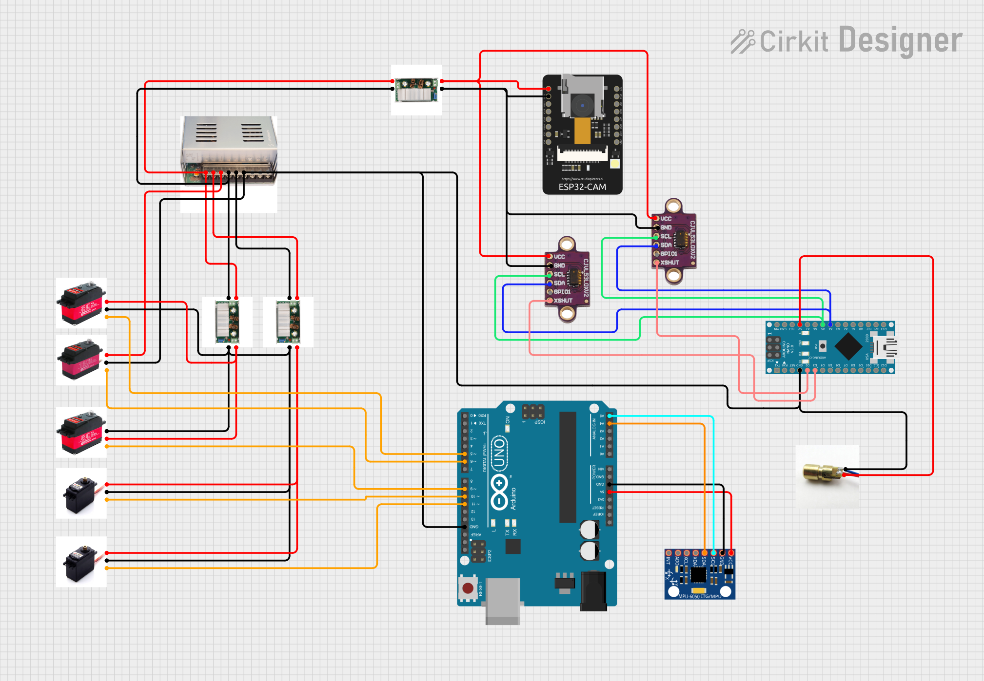
Circuit Documentation
Summary
The circuit in question appears to be a complex system designed to control multiple servo motors, interface with sensors, and manage power distribution. It includes a DC-to-DC converter for voltage regulation, a power supply unit, several servo motors of varying torque capacities, sensor modules, and microcontroller units for control logic. The circuit is likely used for a robotics or automation project where precise movement and environmental sensing are required.
Component List
Power Components
- 12V/8A DC-to-DC Converter: Converts input voltage to a stable 12V output with up to 8A of current.
- DC12V/30A Power Supply: Provides a 12V output with a high current capacity of up to 30A.
Actuators
- 80 Kg/cm DS Servo Motor: A high-torque servo motor capable of delivering up to 80 Kg/cm of torque.
- 150Kg/cm DSG Servo: A heavy-duty servo motor with a torque capacity of up to 150 Kg/cm.
- FS5109M Servo Motor: A standard servo motor for general-purpose applications.
Sensors
- MPU-6050: A motion processing unit that includes a gyroscope and an accelerometer.
- vl53l0xv2: A time-of-flight distance sensor module.
- ESP32 - CAM: A camera module with Wi-Fi capabilities, suitable for IoT applications.
Microcontrollers
- Arduino UNO: A microcontroller board based on the ATmega328P, widely used for prototyping.
- Arduino Nano: A compact microcontroller board based on the ATmega328, suitable for embedding into projects.
Output Devices
- Laser Diode: An electronic component that emits laser light when powered.
Wiring Details
Power Distribution
- DC12V/30A Power Supply supplies power to the DC-to-DC Converters and directly to the 150Kg/cm DSG Servo.
Servo Motors
- 80 Kg/cm DS Servo Motors are powered by the DC-to-DC Converters and controlled by the Arduino UNO.
- 150Kg/cm DSG Servo is powered directly by the Power Supply and controlled by the Arduino UNO.
- FS5109M Servo Motors are powered by the DC-to-DC Converters and controlled by the Arduino UNO.
Sensors
- MPU-6050 is powered by the 5V output from the Arduino UNO and communicates via the I2C interface.
- vl53l0xv2 sensors are powered by the DC-to-DC Converter and communicate with the Arduino Nano via I2C, with additional GPIO for shutdown control.
- ESP32 - CAM is powered by the DC-to-DC Converter.
Output Devices
- Laser Diode is powered by the 5V output from the Arduino Nano.
Documented Code
Arduino UNO Code
void setup() {
  // put your setup code here, to run once:

}

void loop() {
  // put your main code here, to run repeatedly:

}
Arduino Nano Code
void setup() {
  // put your setup code here, to run once:

}

void loop() {
  // put your main code here, to run repeatedly:

}
(Note: The provided code for the microcontrollers is a template and does not contain any specific logic for controlling the circuit components. Additional programming will be required to achieve the desired functionality.)