
Arduino UNO Based Access Control System with Fingerprint and RFID Authentication
View and Edit Project In Cirkit Designer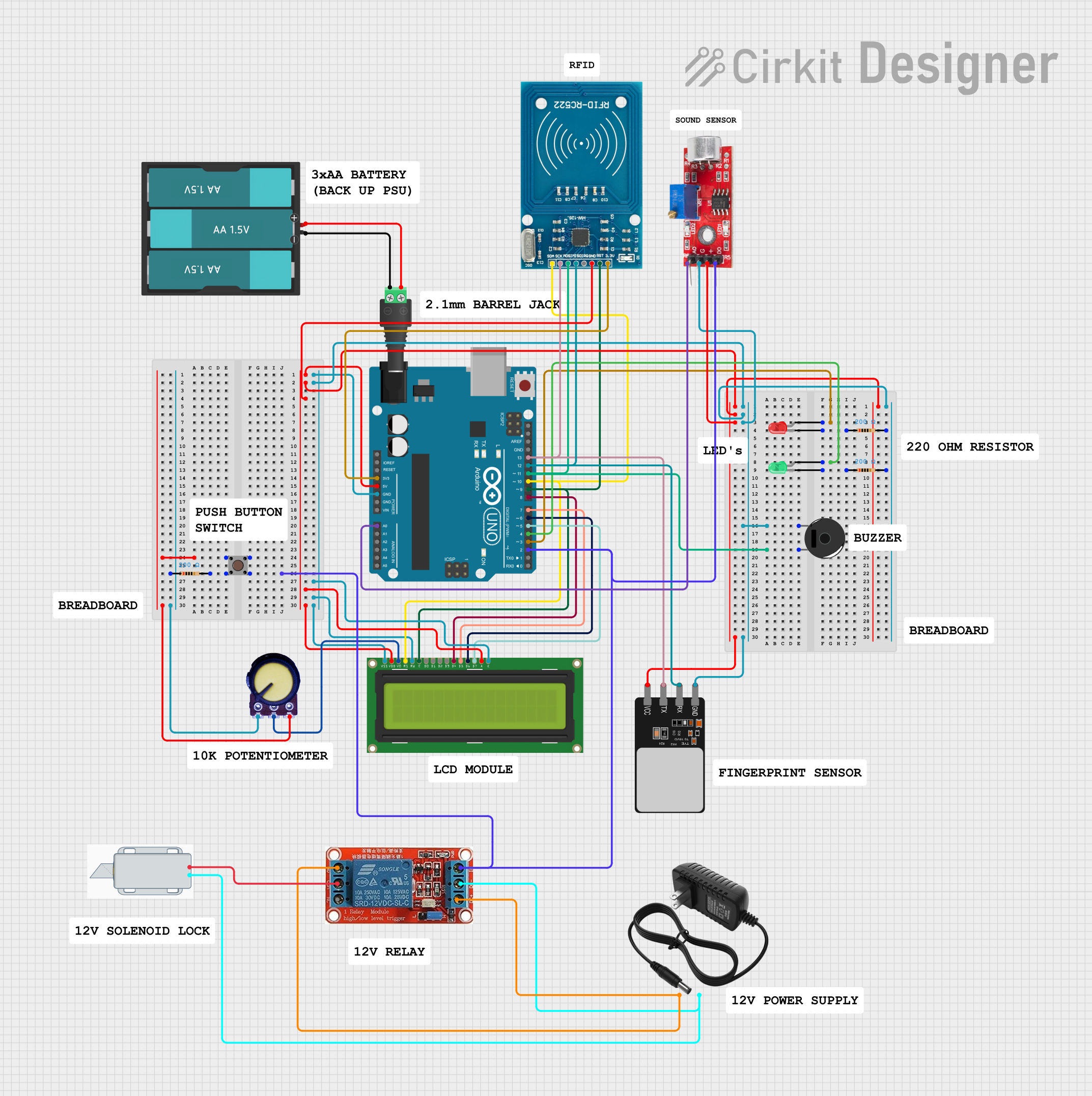
Circuit Documentation
Summary
The circuit is designed to control access through a solenoid lock, which can be unlocked by either a recognized fingerprint, an RFID card, or a certain level of sound detected by a sound sensor. The system uses an Arduino UNO as the central microcontroller to process inputs from the fingerprint scanner, RFID-RC522 module, and sound sensor. It provides feedback to the user through an LCD display, a red LED, a green LED, and a piezo buzzer. The circuit also includes a pushbutton, a potentiometer for LCD contrast adjustment, and resistors for current limiting purposes.
Component List
Microcontroller
- Arduino UNO: The main controller used to interface with the sensors, display, and actuator.
Actuators
- 12V Solenoid Lock: An electrically-controlled lock that can be opened by applying voltage.
- Piezo Buzzer: An electronic device that emits a tone when voltage is applied.
- LED: Two Pin (red): A red light-emitting diode used as an indicator.
- LED: Two Pin (green): A green light-emitting diode used as an indicator.
Sensors
- Fingerprint Scanner: A biometric sensor that captures fingerprints for identification.
- RFID-RC522: An RFID reader/writer module for contactless communication using radio frequencies.
- Sound Sensor: A module that detects sound levels in the environment.
Display
- LCD Display 16x2: A liquid crystal display that shows text information.
Input
- Pushbutton: A button that allows user interaction with the circuit.
Power Supply
- 12v power supply: Provides the necessary voltage for the solenoid lock and relay.
- Battery AAx3 4.5V: Provides power to the circuit.
- 2.1mm Barrel Jack with Terminal Block: Connects the external power supply to the circuit.
Miscellaneous
- Potentiometer: Used to adjust the contrast of the LCD display.
- 12v Relay: An electrically operated switch that controls the solenoid lock.
- Resistor: Used for current limiting to protect LEDs and the piezo buzzer.
Wiring Details
Arduino UNO
- D2: Connected to the relay module (IN) and pushbutton (Pin 2).
- D3: Connected to the anode of the red LED.
- D4: Connected to the anode of the green LED.
- D5-D10: Connected to the LCD display for data and control signals.
- D11: Connected to the piezo buzzer.
- D12: Connected to the RX pin of the fingerprint scanner and MISO of RFID-RC522.
- D13: Connected to the TX pin of the fingerprint scanner and SCK of RFID-RC522.
- A0: Connected to the analog output of the sound sensor.
- 3.3V: Connected to the VCC of the RFID-RC522.
- 5V: Connected to the VCC pins of the sound sensor, fingerprint scanner, and LCD display.
- GND: Common ground for various components.
12V Solenoid Lock
- +: Connected to the COM pin of the relay module.
- -: Connected to the negative terminal of the 12v power supply and DC- of the relay module.
LCD Display 16x2
- RS, E, DB4-DB7: Connected to Arduino pins D10, D9, D8, D7, D6, D5 respectively.
- VSS, RW, LEDK: Connected to GND.
- LEDA, VDD: Connected to 5V.
- VO: Connected to the output of the potentiometer.
Piezo Buzzer
- pin 1: Connected to Arduino pin D11.
- pin 2: Connected to GND through a 200 Ohm resistor.
Pushbutton
- Pin 1 (in): Connected to GND through a 200 Ohm resistor.
- Pin 2 (in): Connected to Arduino pin D2.
Potentiometer
- VCC: Connected to the pushbutton (Pin 3).
- Output: Connected to the VO pin of the LCD display.
- GND: Connected to GND.
LED: Two Pin (red)
- anode: Connected to Arduino pin D3.
- cathode: Connected to GND through a 200 Ohm resistor.
LED: Two Pin (green)
- anode: Connected to Arduino pin D4.
- cathode: Connected to GND through a 200 Ohm resistor.
12v Relay
- IN: Connected to Arduino pin D2.
- COM: Connected to the positive terminal of the solenoid lock.
- NO: Connected to the positive terminal of the 12v power supply.
- NC: Not used in this circuit.
- DC+: Connected to the positive terminal of the 12v power supply.
- DC-: Connected to the negative terminal of the 12v power supply.
Power Supply
- 12v power supply: Positive and negative terminals connected to the relay module and solenoid lock.
- Battery AAx3 4.5V: Connected to the barrel jack with terminal block.
- 2.1mm Barrel Jack with Terminal Block: Interfaces the battery pack with the circuit.
Documented Code
#include <Adafruit_Fingerprint.h>
#include <LiquidCrystal.h>
#include <SPI.h>
#include <MFRC522.h>

// Pin Definitions
const int relayPin = 2; // Relay control pin
const int redLEDPin = 3; // Red LED pin
const int greenLEDPin = 4; // Green LED pin
const int buzzerPin = 11; // Buzzer pin
const int soundSensorPin = A0; // Analog pin for sound sensor

// LCD Pins
LiquidCrystal lcd(10, 9, 8, 7, 6, 5);

// Fingerprint Sensor Pins
SoftwareSerial mySerial(12, 13); // RX, TX
Adafruit_Fingerprint finger = Adafruit_Fingerprint(&mySerial);

// RFID Pins
#define SS_PIN  10  // RFID SS/SDA Pin
#define RST_PIN 5   // RFID RST Pin
MFRC522 rfid(SS_PIN, RST_PIN);

// Variables
int soundThreshold = 500;  // Sound threshold for detection

void setup() {
  // Initialize Serial Monitor
  Serial.begin(9600);

  // Initialize LCD
  lcd.begin(16, 2);
  lcd.clear();

  // Initialize Fingerprint Sensor
  finger.begin(57600);
  if (finger.verifyPassword()) {
    Serial.println("Fingerprint sensor detected.");
    lcd.print("Fingerprint ready");
    delay(2000);
  } else {
    Serial.println("Fingerprint sensor not detected.");
    lcd.print("Sensor failure");
    while (1);
  }

  // Initialize RFID
  SPI.begin();
  rfid.PCD_Init();
  Serial.println("RFID ready");

  // Set Pin Modes
  pinMode(relayPin, OUTPUT);
  pinMode(redLEDPin, OUTPUT);
  pinMode(greenLEDPin, OUTPUT);
  pinMode(buzzerPin, OUTPUT);
  pinMode(soundSensorPin, INPUT);

  // Lock the door initially
  lockDoor();
}

void loop() {
  int fingerprintID = getFingerprintID();
  bool rfidDetected = checkRFID();
  int soundLevel = analogRead(soundSensorPin);

  // Debugging prints
  Serial.print("Fingerprint ID: ");
  Serial.println(fingerprintID);
  Serial.print("RFID Detected: ");
  Serial.println(rfidDetected);
  Serial.print("Sound Level: ");
  Serial.println(soundLevel);

  if (fingerprintID >= 0) {
    // Fingerprint recognized
    lcd.clear();
    lcd.print("FINGERPRINT");
    lcd.setCursor(0, 1);
    lcd.print("RECOGNISED");
    delay(5000);
    unlockDoor();
  } else if (rfidDetected) {
    // RFID card detected
    lcd.clear();
    lcd.print("RFID CARD");
    lcd.setCursor(0, 1);
    lcd.print("RECOGNISED");
    delay(5000);
    unlockDoor();
  } else if (soundLevel > soundThreshold) {
    // Sound detected above threshold
    lcd.clear();
    lcd.print("SOUND DETECTED");
    delay(5000);
    unlockDoor();
  } else {
    // No valid input, keep door locked
    lcd.clear();
    lcd.print("ACCESS DENIED");
    delay(5000);
    lockDoor();
  }
}

// Unlock the door
void unlockDoor() {
  digitalWrite(relayPin, HIGH);
  lcd.clear();
  lcd.print("DOOR OPEN");

  // Activate the buzzer and green LED
  digitalWrite(greenLEDPin, HIGH);
  tone(buzzerPin, 1000); // 1000 Hz frequency
  delay(4000); // Buzzer on for 4 seconds
  noTone(buzzerPin);
  digitalWrite(greenLEDPin, LOW);
}

// Lock the door
void lockDoor() {
  digitalWrite(relayPin, LOW);
  lcd.clear();