
Arduino Nano Controlled NRF24L01 Wireless Communication Module
View and Edit Project In Cirkit Designer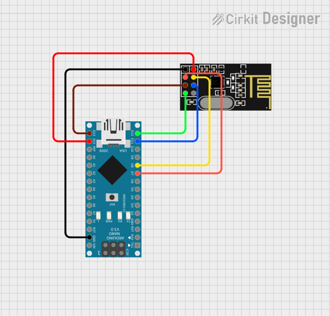
Circuit Documentation
Summary of the Circuit
This circuit integrates an Arduino Nano microcontroller with an NRF24L01 wireless transceiver module. The purpose of this circuit is to enable wireless communication capabilities for the Arduino Nano using the NRF24L01 module. The Arduino Nano serves as the central processing unit, controlling the NRF24L01 module to send and receive data wirelessly.
Component List
Arduino Nano
- Description: A compact microcontroller board based on the ATmega328P, featuring digital and analog I/O pins.
- Purpose: Acts as the main controller for the circuit, executing the embedded code and interfacing with the NRF24L01 module.
NRF24L01
- Description: A 2.4GHz wireless transceiver module capable of transmitting and receiving data at high speeds.
- Purpose: Provides wireless communication capabilities to the circuit when controlled by the Arduino Nano.
Wiring Details
Arduino Nano
- D11/MOSI: Connected to the MOSI pin of the NRF24L01 for SPI data transmission.
- D8: Connected to the CSN pin of the NRF24L01 to select the device on the SPI bus.
- 3V3: Provides power to the VCC (3V) pin of the NRF24L01.
- GND: Connected to the GND pin of the NRF24L01 for a common ground reference.
- D7: Connected to the CE pin of the NRF24L01 to enable the chip for communication.
- D13/SCK: Connected to the SCK pin of the NRF24L01 for SPI clock signal.
- D12/MISO: Connected to the MISO pin of the NRF24L01 for SPI data reception.
NRF24L01
- MOSI: Connected to D11/MOSI on the Arduino Nano for SPI data transmission.
- CSN: Connected to D8 on the Arduino Nano to select the device on the SPI bus.
- VCC (3V): Powered by the 3V3 output from the Arduino Nano.
- GND: Shares a common ground with the Arduino Nano.
- CE: Connected to D7 on the Arduino Nano to enable the chip for communication.
- SCK: Connected to D13/SCK on the Arduino Nano for SPI clock signal.
- MISO: Connected to D12/MISO on the Arduino Nano for SPI data reception.
Documented Code
Arduino Nano Code (sketch.ino)
void setup() {
  // put your setup code here, to run once:

}

void loop() {
  // put your main code here, to run repeatedly:

}
This code provides the basic structure for the Arduino sketch. The setup() function is intended to contain initialization code that runs once at the start, such as configuring the SPI interface and setting pin modes. The loop() function is designed to contain the main logic of the program, which will run repeatedly, handling the wireless communication through the NRF24L01 module.
Additional Notes
- The provided code is a template and requires further implementation for specific wireless communication tasks.
- The IRQ pin of the NRF24L01 is not used in this circuit configuration.
- The actual functionality of the NRF24L01 will depend on the code written in the
setup()andloop()functions, which should include the initialization of the SPI interface and the necessary logic for sending and receiving data wirelessly.
This documentation provides an overview of the circuit components, their wiring, and the basic code structure for operating the Arduino Nano with the NRF24L01 wireless transceiver module. Further development and testing are required to achieve the desired wireless communication functionality.