
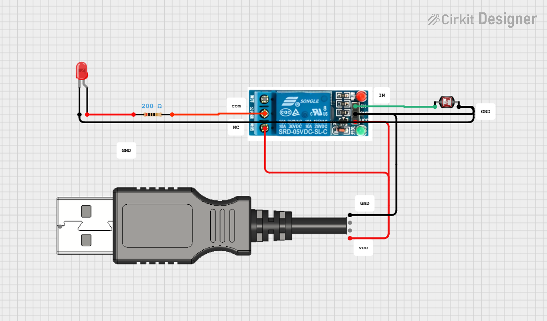
Circuit Documentation
Summary
This circuit involves a 5V relay, a red LED, a USB plug, a photocell (LDR), and a resistor. The circuit is designed to control the LED based on the light intensity detected by the photocell. The USB plug provides power to the circuit.
Component List
5V Relay
- Pins: Normally Open, Common terminal, Normally Closed, In, GND, VCC
- Description: A relay that operates at 5V.
- Purpose: Used to switch the LED on and off based on the input from the photocell.
LED: Two Pin (red)
- Pins: Cathode, Anode
- Description: A red LED.
- Purpose: Indicates the status of the circuit.
USB Plug
- Pins: GND, D+, D-, 5V+, Out
- Description: A standard USB plug.
- Purpose: Provides 5V power to the circuit.
Photocell (LDR)
- Pins: Pin 0, Pin 1
- Description: A light-dependent resistor.
- Purpose: Detects the ambient light level.
Resistor
- Pins: Pin1, Pin2
- Description: A resistor with a resistance of 200 Ohms.
- Purpose: Limits the current to the LED.
Wiring Details
5V Relay
- Common terminal is connected to Pin2 of the Resistor.
- Normally Closed is connected to 5V+ of the USB Plug.
- VCC is connected to 5V+ of the USB Plug.
- In is connected to Pin 0 of the Photocell (LDR).
- GND is connected to GND of the USB Plug and Pin 1 of the Photocell (LDR).
LED: Two Pin (red)
- Cathode is connected to GND of the USB Plug and Pin 1 of the Photocell (LDR).
- Anode is connected to Pin1 of the Resistor.
USB Plug
- 5V+ is connected to Normally Closed and VCC of the 5V Relay.
- GND is connected to Cathode of the LED, GND of the 5V Relay, and Pin 1 of the Photocell (LDR).
Photocell (LDR)
- Pin 0 is connected to In of the 5V Relay.
- Pin 1 is connected to GND of the USB Plug, Cathode of the LED, and GND of the 5V Relay.
Resistor
- Pin1 is connected to Anode of the LED.
- Pin2 is connected to Common terminal of the 5V Relay.
Code
There is no code associated with this circuit.