
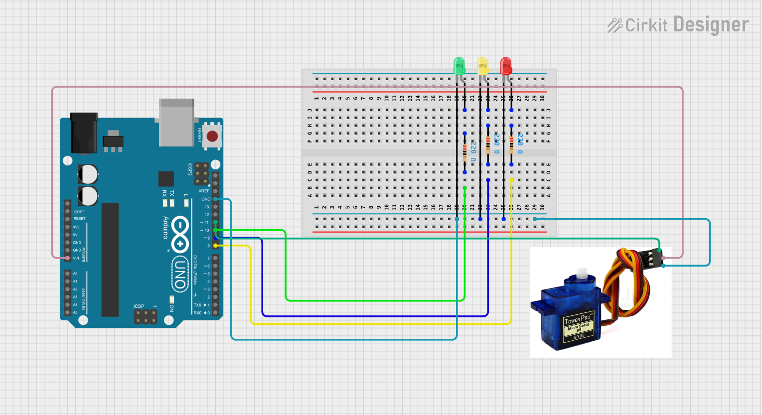
Circuit Documentation
Summary of the Circuit
This circuit is designed to interface an Arduino UNO with a servo motor and three LEDs (red, green, and yellow). Each LED is connected to the Arduino through a 220-ohm resistor to limit the current. The servo motor is controlled by one of the digital pins of the Arduino. The ground connections are shared among all components, and the servo motor is powered directly from the Arduino's voltage input pin.
Component List
Arduino UNO
- Microcontroller board based on the ATmega328P
- It has 14 digital input/output pins, 6 analog inputs, a 16 MHz quartz crystal, a USB connection, a power jack, an ICSP header, and a reset button.
LED: Two Pin (red)
- A red light-emitting diode (LED) with an anode and cathode pin.
LED: Two Pin (green)
- A green light-emitting diode (LED) with an anode and cathode pin.
LED: Two Pin (yellow)
- A yellow light-emitting diode (LED) with an anode and cathode pin.
Resistor (220 Ohms)
- A resistor with a resistance of 220 ohms, used to limit the current through the LEDs.
Servo Motor
- A motor capable of precise control of angular position, equipped with signal, power (VCC), and ground (GND) connections.
Wiring Details
Arduino UNO
- Vin connected to the servo motor's VCC.
- GND connected to the cathodes of all three LEDs and the GND of the servo motor.
- D11 connected to the servo motor's signal pin.
- D10 connected to a 220-ohm resistor leading to the anode of the green LED.
- D9 connected to a 220-ohm resistor leading to the anode of the yellow LED.
- D8 connected to a 220-ohm resistor leading to the anode of the red LED.
LED: Two Pin (red)
- Anode connected to a 220-ohm resistor.
- Cathode connected to the Arduino UNO's GND.
LED: Two Pin (green)
- Anode connected to a 220-ohm resistor.
- Cathode connected to the Arduino UNO's GND.
LED: Two Pin (yellow)
- Anode connected to a 220-ohm resistor.
- Cathode connected to the Arduino UNO's GND.
Resistor (220 Ohms)
- One pin connected to the Arduino UNO's digital pins (D10, D9, or D8).
- The other pin connected to the anode of the corresponding LED (green, yellow, or red).
Servo Motor
- Signal connected to the Arduino UNO's D11.
- VCC connected to the Arduino UNO's Vin.
- GND connected to the Arduino UNO's GND.
Documented Code
Arduino UNO Code (sketch.ino)
void setup() {
  // put your setup code here, to run once:

}

void loop() {
  // put your main code here, to run repeatedly:

}
Additional Notes (documentation.txt)
No additional code documentation provided.