
ESP32-CAM Controlled Surveillance Robot with Wi-Fi and Servo Pan/Tilt Mechanism
View and Edit Project In Cirkit Designer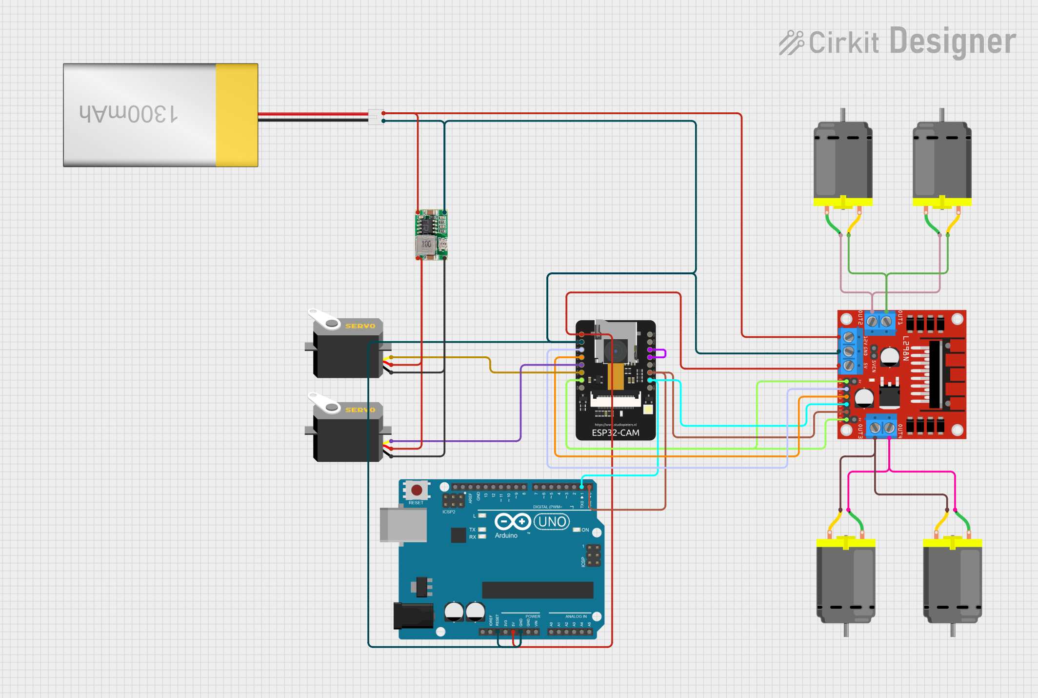
Circuit Documentation
Summary
This circuit is designed to control a vehicle with two DC motors for movement, two servos for directional control, and an ESP32-CAM module for wireless communication and camera functionality. The L298N DC motor driver is used to drive the DC motors, and a Mini 360 Buck Converter is included to regulate power. The system is powered by a LiPoly Battery and controlled by an ESP32-CAM microcontroller with an additional Arduino UNO microcontroller for auxiliary control tasks.
Component List
L298N DC Motor Driver
- Description: A motor driver capable of driving a pair of DC motors.
- Pins: OUT1, OUT2, 12V, GND, 5V, OUT3, OUT4, 5V-ENA-JMP-I, 5V-ENA-JMP-O, +5V-J1, +5V-J2, ENA, IN1, IN2, IN3, IN4, ENB
DC Motor (x4)
- Description: A standard DC motor for driving the vehicle.
- Pins: pin 1, pin 2
ESP32 - CAM
- Description: A microcontroller with Wi-Fi capability and camera support.
- Pins: 5V, GND, IO12, IO13, IO15, IO14, IO2, IO4, VOT, VOR, VCC, IO0, IO16, 3V3
Servo (x2)
- Description: A servo motor for directional control.
- Pins: gnd, vcc, pulse
Mini 360 Buck Converter
- Description: A DC-DC step-down converter to regulate power supply.
- Pins: IN-, OUT-, OUT+, IN+
LiPoly Battery (1300mAh)
- Description: A lithium polymer battery to power the circuit.
- Pins: positive, negative
Arduino UNO
- Description: A microcontroller board based on the ATmega328P.
- Pins: UNUSED, IOREF, Reset, 3.3V, 5V, GND, Vin, A0, A1, A2, A3, A4, A5, SCL, SDA, AREF, D13, D12, D11, D10, D9, D8, D7, D6, D5, D4, D3, D2, D1, D0
Wiring Details
L298N DC Motor Driver
- OUT1, OUT2 connected to DC Motor 1
- OUT3, OUT4 connected to DC Motor 2
- 12V connected to Mini 360 Buck Converter (OUT+)
- GND connected to system ground
- 5V connected to Arduino UNO (5V)
- ENA, ENB connected to ESP32 - CAM (IO2)
- IN1 connected to ESP32 - CAM (IO12)
- IN2 connected to ESP32 - CAM (IO13)
- IN3 connected to Arduino UNO (D1)
- IN4 connected to Arduino UNO (D0)
DC Motors
- Motor 1: pin 1 connected to L298N (OUT2), pin 2 connected to L298N (OUT1)
- Motor 2: pin 1 connected to L298N (OUT4), pin 2 connected to L298N (OUT3)
ESP32 - CAM
- 5V connected to Arduino UNO (5V)
- GND connected to system ground
- IO12, IO13 connected to L298N (IN1, IN2)
- IO15, IO14 connected to Servos (pulse)
- IO2 connected to L298N (ENA, ENB)
- IO0 connected to GND (for programming mode)
- VOT, VOR connected to Arduino UNO (D1, D0)
Servos
- Servo 1: pulse connected to ESP32 - CAM (IO14), vcc connected to Mini 360 Buck Converter (OUT+), gnd connected to system ground
- Servo 2: pulse connected to ESP32 - CAM (IO15), vcc connected to Mini 360 Buck Converter (OUT+), gnd connected to system ground
Mini 360 Buck Converter
- IN+ connected to LiPoly Battery (positive)
- OUT+ connected to L298N (12V) and Servos (vcc)
- IN-, OUT- connected to system ground
LiPoly Battery
- positive connected to Mini 360 Buck Converter (IN+)
- negative connected to system ground
Arduino UNO
- Reset connected to GND (for reset functionality)
- 5V connected to L298N (5V) and ESP32 - CAM (5V)
- GND connected to system ground
- D0, D1 connected to L298N (IN4, IN3)
Documented Code
ESP32 - CAM Code (sketch.ino)
#include "esp_camera.h"
#include <Arduino.h>
#include <WiFi.h>
#include <AsyncTCP.h>
#include <ESPAsyncWebServer.h>
#include <iostream>
#include <sstream>
#include <ESP32Servo.h>

// ... (Code truncated for brevity)

void setup(void) {
  // Setup pin modes, initialize servos, PWM, and camera
  // Start WiFi and web server
  // ... (Code truncated for brevity)
}

void loop() {
  // Cleanup WebSocket clients and send camera picture
  // ... (Code truncated for brevity)
}
This code initializes the ESP32-CAM module, sets up the web server, and handles WebSocket events for camera streaming and car control. It also includes functions to control the motors and servos based on WebSocket messages.
Arduino UNO Code (sketch.ino)
// The Arduino UNO code is similar to the ESP32-CAM code and is used for auxiliary control.
// ... (Code truncated for brevity)

void setup(void) {
  // Setup pin modes and initialize WiFi and web server
  // ... (Code truncated for brevity)
}

void loop() {
  // Cleanup WebSocket clients and send camera picture
  // ... (Code truncated for brevity)
}
The Arduino UNO code is not provided in full detail but is expected to perform similar functions as the ESP32-CAM, likely for redundancy or additional control features.
(Note: The actual code is much longer and includes detailed functions for motor control, WebSocket communication, and camera handling. The provided snippets are summaries to illustrate the functionality.)