Cirkit Designer
Your all-in-one circuit design IDE
Home /
Project Documentation
Arduino Nano Motor Controller with DRV8833 Driver
Circuit Documentation
Summary
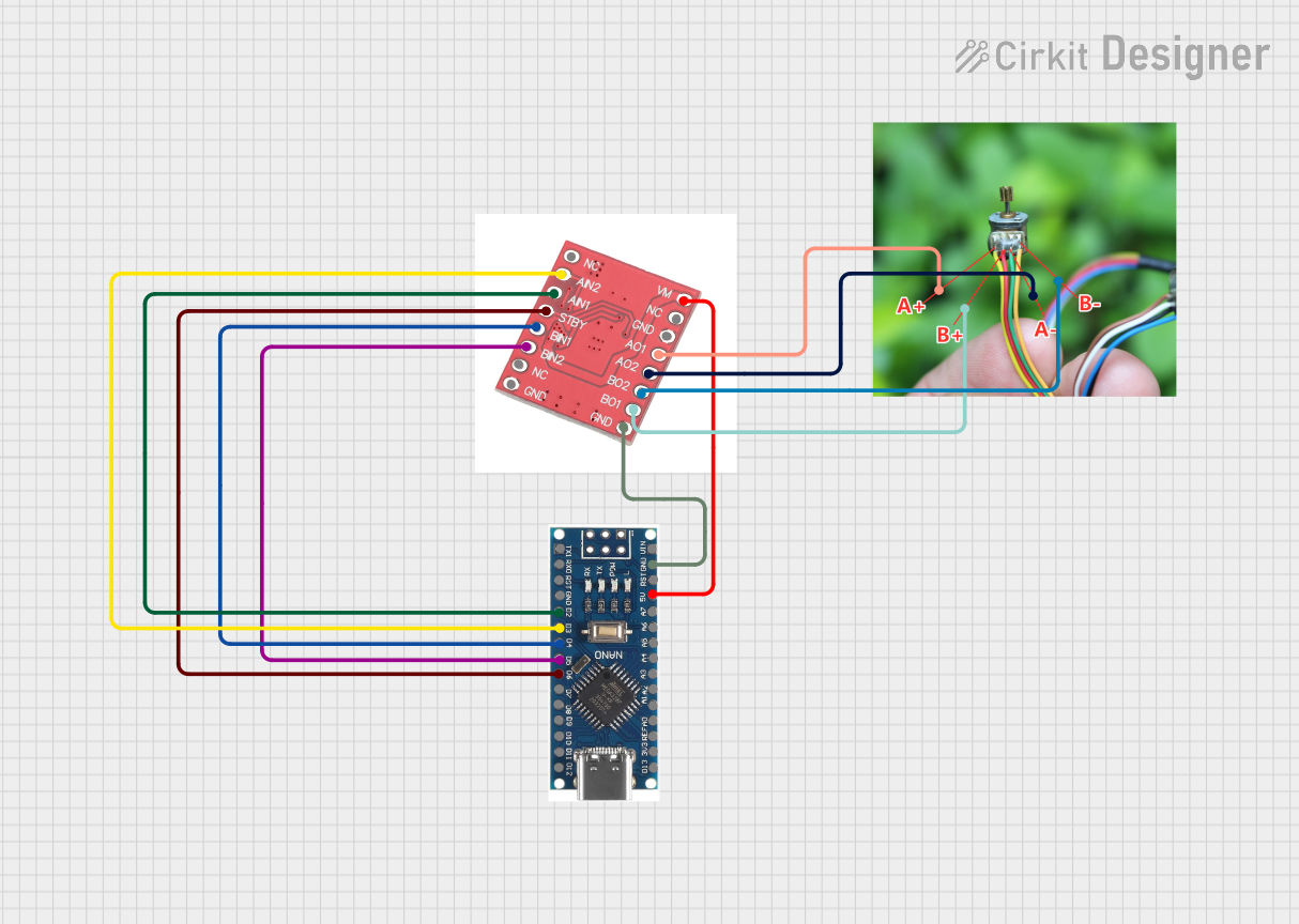
This document provides a detailed overview of a circuit that includes a Nano 3.0 ATmega328P Type-C USB CH340 Controller Board, a DRV8833 motor driver, and a 2-phase 4-wire motor. The circuit is designed to control the motor using the microcontroller and motor driver.
Component List
Nano 3.0 ATmega328P Type-C USB CH340 Controller Board
- Description: A microcontroller board based on the ATmega328P, featuring a Type-C USB interface and CH340 USB-to-serial converter.
- Pins: D13, 3V3, REF, A0, A1, A2, A3, A4, A5, A6, A7, 5V, RST, GND, VIN, D11, D10, D9, D8, D7, D6, D5, D4, D3, D2, RX0, TX1, D12
DRV8833
- Description: A dual H-bridge motor driver capable of driving two DC motors or one stepper motor.
- Pins: NC, AIN2, AIN1, STBY, BIN1, BIN2, GND, VM, AO1, AO2, BO2, BO1
2-phase 4-wire motor
- Description: A stepper motor with 2 phases and 4 wires.
- Pins: A+, B+, A-, B-
Wiring Details
Nano 3.0 ATmega328P Type-C USB CH340 Controller Board
- 5V is connected to VM of the DRV8833.
- GND is connected to GND of the DRV8833.
- D6 is connected to STBY of the DRV8833.
- D5 is connected to BIN2 of the DRV8833.
- D4 is connected to BIN1 of the DRV8833.
- D3 is connected to AIN2 of the DRV8833.
- D2 is connected to AIN1 of the DRV8833.
DRV8833
- VM is connected to 5V of the Nano 3.0 ATmega328P.
- GND is connected to GND of the Nano 3.0 ATmega328P.
- STBY is connected to D6 of the Nano 3.0 ATmega328P.
- BIN2 is connected to D5 of the Nano 3.0 ATmega328P.
- BIN1 is connected to D4 of the Nano 3.0 ATmega328P.
- AIN2 is connected to D3 of the Nano 3.0 ATmega328P.
- AIN1 is connected to D2 of the Nano 3.0 ATmega328P.
- AO1 is connected to A+ of the 2-phase 4-wire motor.
- AO2 is connected to A- of the 2-phase 4-wire motor.
- BO2 is connected to B- of the 2-phase 4-wire motor.
- BO1 is connected to B+ of the 2-phase 4-wire motor.
2-phase 4-wire motor
- A+ is connected to AO1 of the DRV8833.
- A- is connected to AO2 of the DRV8833.
- B- is connected to BO2 of the DRV8833.
- B+ is connected to BO1 of the DRV8833.
Code
No code is provided for this circuit.