
Arduino Mega ADK Water Level Monitoring System with LCD Display
View and Edit Project In Cirkit Designer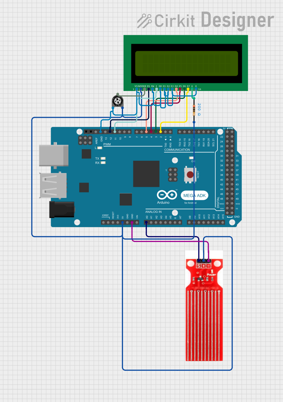
Circuit Documentation
Summary
This circuit is designed to monitor water levels using a water sensor and display the readings on a 16x2 LCD. The core of the circuit is an Arduino Mega ADK (Rev3) microcontroller which reads the analog signal from the water sensor and processes the data to display the water level as a percentage on the LCD. The LCD's contrast is adjustable via a trimmer potentiometer. A resistor is also included in the circuit, likely for current limiting purposes.
Component List
Water Sensor
- Pins: Signal, VCC, GND
- Description: A sensor that detects the presence of water and outputs an analog signal proportional to the water level.
Arduino Mega ADK (Rev3)
- Pins: Multiple digital and analog pins, power, and ground pins.
- Description: A microcontroller board based on the ATmega2560, with numerous digital and analog I/O pins for interfacing with various sensors and actuators.
16X2 LCD
- Pins: VSS, VDD, V0, RS, RW, E, D0-D7, A, K
- Description: A liquid crystal display capable of displaying two lines of 16 characters each.
Trimmer Potentiometer
- Pins: leg1, wiper, leg2
- Description: A variable resistor with a 10k Ohm value, used to adjust the contrast of the LCD.
Resistor
- Pins: pin1, pin2
- Description: A fixed resistor with a value of 200 Ohms, likely used for current limiting.
Wiring Details
Water Sensor
- Signal connected to Arduino Mega ADK (Rev3) Analog Pin A0
- VCC connected to 5V power supply from Arduino Mega ADK (Rev3)
- GND connected to ground on Arduino Mega ADK (Rev3)
Arduino Mega ADK (Rev3)
- A0 connected to Water Sensor Signal
- 5V connected to Water Sensor VCC, Trimmer Potentiometer leg2, and 16X2 LCD VDD
- GND connected to Water Sensor GND, Trimmer Potentiometer leg1, 16X2 LCD VSS, K, RW, D0-D3
- D12 PWM connected to 16X2 LCD RS
- D11 PWM connected to 16X2 LCD E
- D2-D5 PWM connected to 16X2 LCD D4-D7 respectively
16X2 LCD
- VSS connected to ground
- VDD connected to 5V power supply
- V0 connected to Trimmer Potentiometer wiper
- RS connected to Arduino Mega ADK (Rev3) Digital Pin D12 PWM
- RW connected to ground
- E connected to Arduino Mega ADK (Rev3) Digital Pin D11 PWM
- D0-D3 connected to ground
- D4-D7 connected to Arduino Mega ADK (Rev3) Digital Pins D5-D2 PWM respectively
- A connected to one end of the Resistor
- K connected to ground
Trimmer Potentiometer
- leg1 connected to ground
- wiper connected to 16X2 LCD V0
- leg2 connected to 5V power supply
Resistor
- pin1 connected to 16X2 LCD A
- pin2 connected to 5V power supply
Documented Code
/*
 * This Arduino Sketch reads the water level from a water sensor and displays
 * the level on a 16x2 LCD. The water sensor is connected to analog pin A0,
 * and the LCD is connected using a standard 4-bit mode.
 */

#include <LiquidCrystal.h>

// Initialize the LCD with the numbers of the interface pins
const int rs = 12, en = 11, d4 = 5, d5 = 4, d6 = 3, d7 = 2;
LiquidCrystal lcd(rs, en, d4, d5, d6, d7);

// Define the pin for the water sensor
const int waterSensorPin = A0;

void setup() {
  // Set up the LCD's number of columns and rows
  lcd.begin(16, 2);
  // Print a message to the LCD
  lcd.print("Water Level:");
}

void loop() {
  // Read the value from the water sensor
  int sensorValue = analogRead(waterSensorPin);
  // Convert the sensor value to a water level percentage
  int waterLevel = map(sensorValue, 0, 1023, 0, 100);
  // Set the cursor to column 0, line 1
  lcd.setCursor(0, 1);
  // Print the water level to the LCD
  lcd.print(waterLevel);
  lcd.print("%");
  // Wait for a second before the next reading
  delay(1000);
}
This code is designed to run on the Arduino Mega ADK (Rev3) and assumes the wiring as detailed above. It initializes the LCD and continuously reads the water level from the sensor, displaying it as a percentage on the LCD.