
ESP8266-Based Accident Detection and GPS Tracking System with I2C LCD Display
View and Edit Project In Cirkit Designer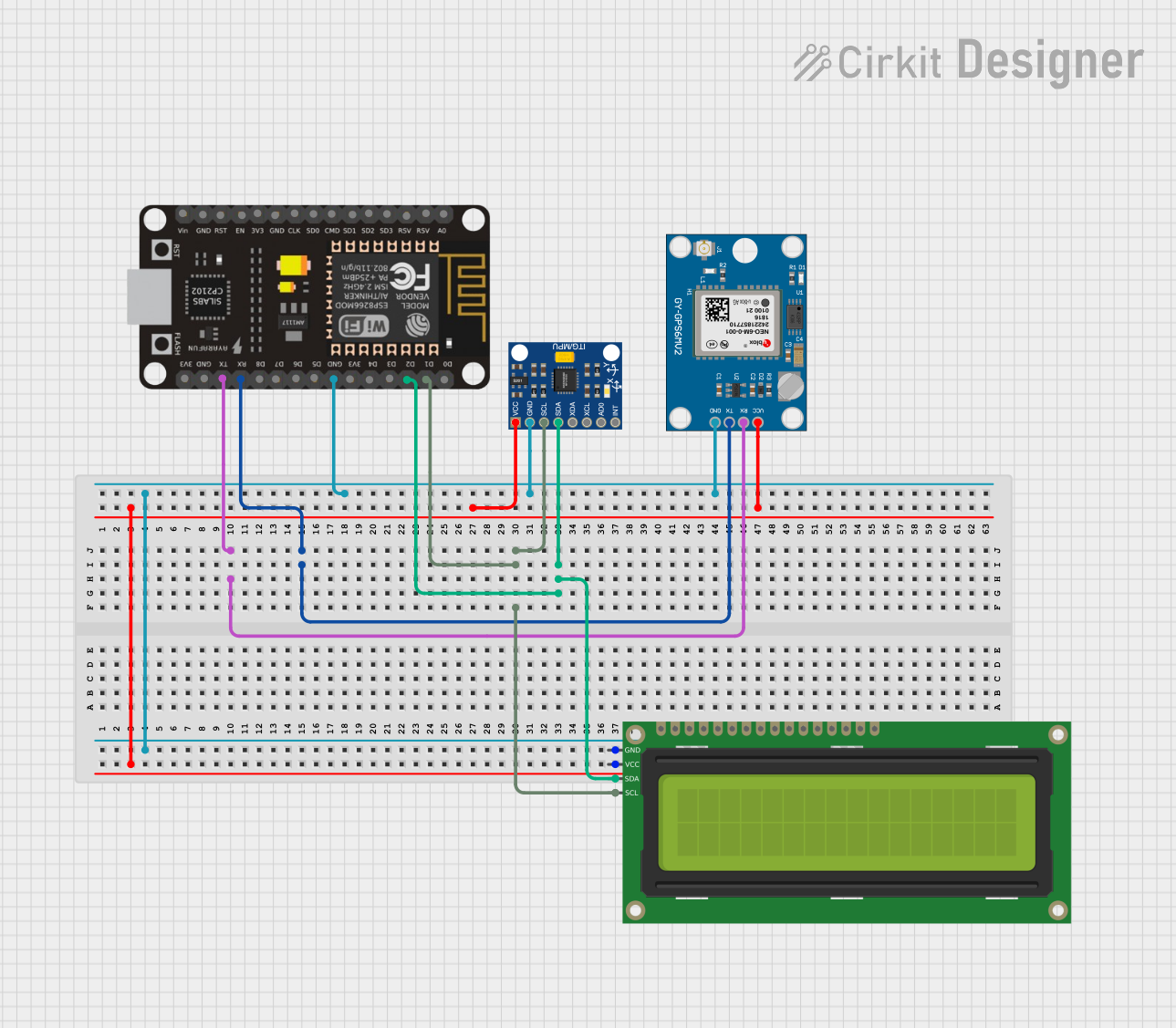
Circuit Documentation
Summary
This document provides a detailed overview of a circuit that integrates an ESP8266 NodeMCU, an InvenSense MPU6050 accelerometer, a Neo 6M GPS module, and a 16x2 I2C LCD display. The circuit is designed to detect accidents using the accelerometer and display relevant information on the LCD while also utilizing GPS data for location tracking.
Component List
InvenSense MPU6050
- Description: 6-axis accelerometer and gyroscope.
- Pins: VCC, GND, SCL, SDA, XDA, XCL, AD0, INT
Neo 6M GPS Module
- Description: GPS module for location tracking.
- Pins: GND, TX, RX, VCC
ESP8266 NodeMCU
- Description: Wi-Fi enabled microcontroller.
- Pins: D0, D1, D2, D3, D4, 3V3, GND, D5, D6, D7, D8, RX, TX, A0, RSV, SD3, SD2, SD1, CMD, SD0, CLK, EN, RST, VIN
16x2 I2C LCD
- Description: 16x2 character LCD with I2C interface.
- Pins: GND, VCC, SDA, SCL
Wiring Details
InvenSense MPU6050
- VCC: Connected to VCC of the 16x2 I2C LCD and Neo 6M GPS Module.
- GND: Connected to GND of the ESP8266 NodeMCU, 16x2 I2C LCD, and Neo 6M GPS Module.
- SCL: Connected to D1 of the ESP8266 NodeMCU and SCL of the 16x2 I2C LCD.
- SDA: Connected to D2 of the ESP8266 NodeMCU and SDA of the 16x2 I2C LCD.
Neo 6M GPS Module
- GND: Connected to GND of the ESP8266 NodeMCU, 16x2 I2C LCD, and InvenSense MPU6050.
- TX: Connected to RX of the ESP8266 NodeMCU.
- RX: Connected to TX of the ESP8266 NodeMCU.
- VCC: Connected to VCC of the 16x2 I2C LCD and InvenSense MPU6050.
ESP8266 NodeMCU
- TX: Connected to RX of the Neo 6M GPS Module.
- RX: Connected to TX of the Neo 6M GPS Module.
- D1: Connected to SCL of the InvenSense MPU6050 and 16x2 I2C LCD.
- D2: Connected to SDA of the InvenSense MPU6050 and 16x2 I2C LCD.
- GND: Connected to GND of the 16x2 I2C LCD, InvenSense MPU6050, and Neo 6M GPS Module.
16x2 I2C LCD
- GND: Connected to GND of the ESP8266 NodeMCU, InvenSense MPU6050, and Neo 6M GPS Module.
- VCC: Connected to VCC of the InvenSense MPU6050 and Neo 6M GPS Module.
- SCL: Connected to D1 of the ESP8266 NodeMCU and SCL of the InvenSense MPU6050.
- SDA: Connected to D2 of the ESP8266 NodeMCU and SDA of the InvenSense MPU6050.
Documented Code
InvenSense MPU6050
sketch.ino
// Pseudo code for accident detection
if (abs(acceleration.x) > threshold || abs(acceleration.y) > threshold || abs(acceleration.z) > threshold) {
    accident_detected = true;
}
Neo 6M GPS Module
sketch.ino
double calculateDistance(lat1, lon1, lat2, lon2) {
    // Implement Haversine formula to calculate distance
    double dLat = (lat2 - lat1) * DEG_TO_RAD;
    double dLon = (lon2 - lon1) * DEG_TO_RAD;
    // Compute the distance using earth radius and return value
    return distance;
}
This documentation provides a comprehensive overview of the circuit, including the components used, their wiring details, and the code implemented for the microcontrollers.