
Arduino Nano RF Remote Controller with Dual Joysticks and Potentiometers
View and Edit Project In Cirkit Designer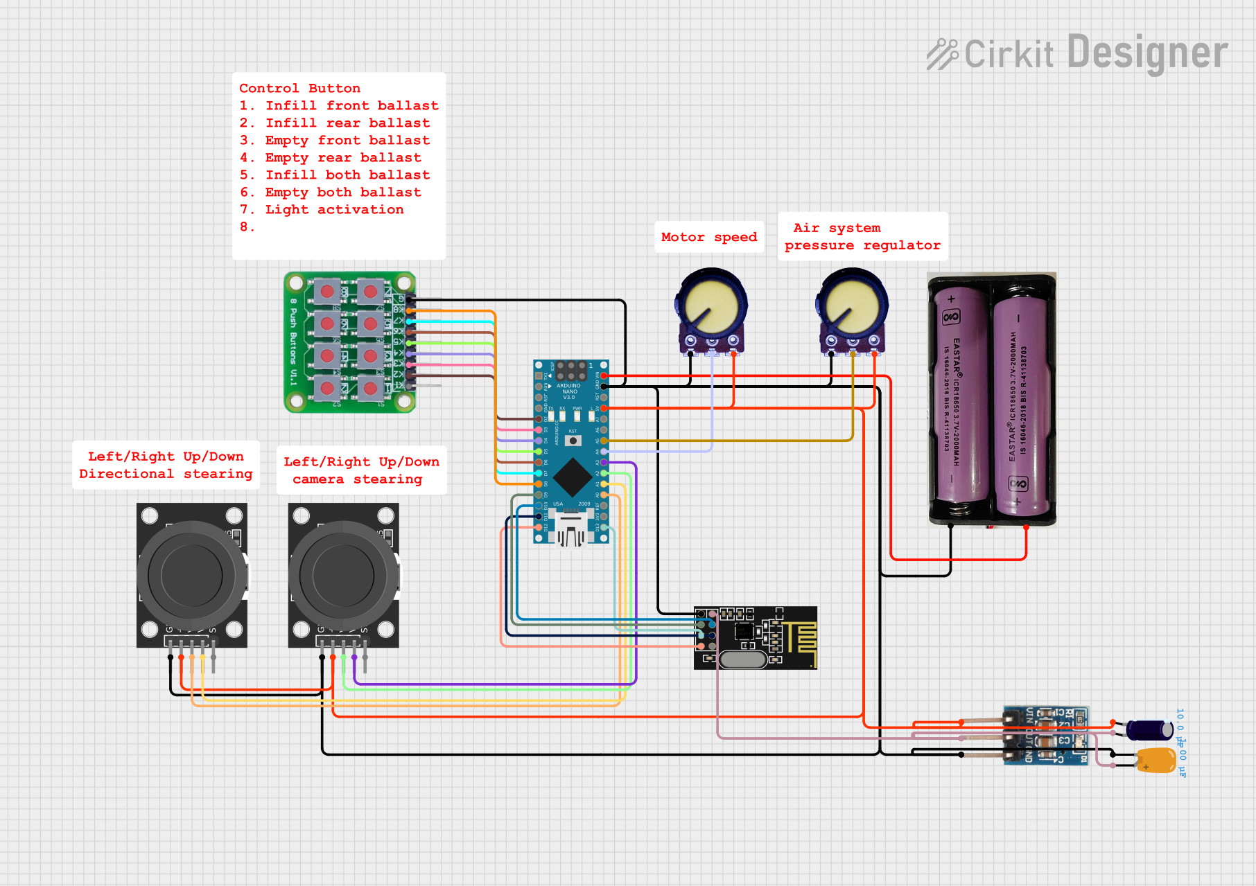
Circuit Documentation
Summary
This document provides a detailed overview of an RF RC controller circuit. The circuit includes two joysticks, seven buttons, two potentiometers, and an NRF24L01 module for wireless communication. The controller is powered by a 7.4V battery and uses an Arduino Nano as the main microcontroller. The circuit is designed for battery operation with optimized power consumption and RF communication stability.
Component List
7.4V Battery
- Pins: +, -
- Description: Power source for the circuit.
KY-023 Dual Axis Joystick Module (2 units)
- Pins: GND, +5V, VRx, VRy, SW
- Description: Joystick module for user input.
8 Push Button Board PCB
- Pins: K1, K2, K3, K4, K5, K6, K7, K8, GROUND
- Description: Board with 8 push buttons for user input.
NRF24L01
- Pins: IRQ (not used), MOSI, CSN, VCC (3V), GND, CE, SCK, MISO
- Description: Wireless communication module.
3.3V Regulator
- Pins: GND, OUT, Vin
- Description: Voltage regulator to provide 3.3V for the NRF24L01 module.
Electrolytic Capacitor
- Pins: +, -
- Description: Capacitor for power stabilization.
- Properties: Capacitance: 0.00001 Farads
Arduino Nano
- Pins: D1/TX, D0/RX, RESET, GND, D2, D3, D4, D5, D6, D7, D8, D9, D10, D11/MOSI, D12/MISO, VIN, 5V, A7, A6, A5, A4, A3, A2, A1, A0, AREF, 3V3, D13/SCK
- Description: Main microcontroller for the circuit.
Tantalum Capacitor
- Pins: +, -
- Description: Capacitor for power stabilization.
- Properties: Capacitance: 0.000001 Farads
Potentiometer (2 units)
- Pins: GND, Output, VCC
- Description: Potentiometer for user input.
Wiring Details
7.4V Battery
- + Pin: Connected to VIN pin of Arduino Nano.
- - Pin: Connected to GND pins of various components.
KY-023 Dual Axis Joystick Module (1st Unit)
- GND Pin: Connected to common ground.
- +5V Pin: Connected to 5V pin of Arduino Nano.
- VRx Pin: Connected to A2 pin of Arduino Nano.
- VRy Pin: Connected to A3 pin of Arduino Nano.
- SW Pin: Not connected.
KY-023 Dual Axis Joystick Module (2nd Unit)
- GND Pin: Connected to common ground.
- +5V Pin: Connected to 5V pin of Arduino Nano.
- VRx Pin: Connected to A0 pin of Arduino Nano.
- VRy Pin: Connected to A1 pin of Arduino Nano.
- SW Pin: Not connected.
8 Push Button Board PCB
- GROUND Pin: Connected to common ground.
- K2 Pin: Connected to D2 pin of Arduino Nano.
- K3 Pin: Connected to D3 pin of Arduino Nano.
- K4 Pin: Connected to D4 pin of Arduino Nano.
- K5 Pin: Connected to D5 pin of Arduino Nano.
- K6 Pin: Connected to D6 pin of Arduino Nano.
- K7 Pin: Connected to D7 pin of Arduino Nano.
- K8 Pin: Connected to D8 pin of Arduino Nano.
NRF24L01
- GND Pin: Connected to common ground.
- VCC (3V) Pin: Connected to OUT pin of 3.3V regulator.
- CE Pin: Connected to D9 pin of Arduino Nano.
- CSN Pin: Connected to D10 pin of Arduino Nano.
- MOSI Pin: Connected to D11/MOSI pin of Arduino Nano.
- MISO Pin: Connected to D12/MISO pin of Arduino Nano.
- SCK Pin: Connected to D13/SCK pin of Arduino Nano.
- IRQ Pin: Not used.
3.3V Regulator
- GND Pin: Connected to common ground.
- OUT Pin: Connected to VCC (3V) pin of NRF24L01.
- Vin Pin: Connected to - pin of Electrolytic Capacitor.
Electrolytic Capacitor
- + Pin: Connected to + pin of Tantalum Capacitor.
- - Pin: Connected to Vin pin of 3.3V regulator.
Arduino Nano
- VIN Pin: Connected to + pin of 7.4V battery.
- GND Pin: Connected to common ground.
- 5V Pin: Connected to +5V pins of Joystick Modules.
- A2 Pin: Connected to VRx pin of 1st Joystick Module.
- A3 Pin: Connected to VRy pin of 1st Joystick Module.
- A0 Pin: Connected to VRx pin of 2nd Joystick Module.
- A1 Pin: Connected to VRy pin of 2nd Joystick Module.
- D2 Pin: Connected to K2 pin of Push Button Board.
- D3 Pin: Connected to K3 pin of Push Button Board.
- D4 Pin: Connected to K4 pin of Push Button Board.
- D5 Pin: Connected to K5 pin of Push Button Board.
- D6 Pin: Connected to K6 pin of Push Button Board.
- D7 Pin: Connected to K7 pin of Push Button Board.
- D8 Pin: Connected to K8 pin of Push Button Board.
- D9 Pin: Connected to CE pin of NRF24L01.
- D10 Pin: Connected to CSN pin of NRF24L01.
- D11/MOSI Pin: Connected to MOSI pin of NRF24L01.
- D12/MISO Pin: Connected to MISO pin of NRF24L01.
- D13/SCK Pin: Connected to SCK pin of NRF24L01.
- A4 Pin: Connected to Output pin of 1st Potentiometer.
- A5 Pin: Connected to Output pin of 2nd Potentiometer.
Tantalum Capacitor
- + Pin: Connected to + pin of Electrolytic Capacitor.
- - Pin: Connected to common ground.
Potentiometer (1st Unit)
- GND Pin: Connected to common ground.
- Output Pin: Connected to A4 pin of Arduino Nano.
- VCC Pin: Connected to - pin of Electrolytic Capacitor.
Potentiometer (2nd Unit)
- GND Pin: Connected to common ground.
- Output Pin: Connected to A5 pin of Arduino Nano.
- VCC Pin: Connected to - pin of Electrolytic Capacitor.
Code Documentation
/*
 * RF RC Controller
 *
 * This Arduino sketch is designed for an RF RC controller with two joysticks,
 * 7 buttons, and 2 potentiometers. The controller communicates with an NRF24L01
 * module to send the state of the inputs to a receiver. Power consumption is
 * optimized for battery operation, and RF communication stability is monitored.
 * If a transmission fails, it is retried 10 times maximum. Every 5 seconds, the
 * transmitter verifies if the receiver is listening. If no confirmation is
 * received, a message saying 'connection lost' is sent.
 */

#include <SPI.h>
#include <nRF24L01.h>
#include <RF24.h>

// NRF24L01 configuration
#define CE_PIN 9
#define CSN_PIN 10
RF24 radio(CE_PIN, CSN_PIN);
const byte address[6] = "00001";

// Joystick pins
const int joy1X = A2;
const int joy1Y = A3;
const int joy2X = A0;
const int joy2Y = A1;

// Button pins
const int buttonPins[7] = {2, 3, 4, 5, 6, 7, 8};

// Potentiometer pins
const int pot1 = A4;
const int pot2 = A5;

// Data structure to hold the state of the inputs
struct DataPacket {
  int joy1X;
  int joy1Y;
  int joy2X;
  int joy2Y;
  int pot1;
  int pot2;
  bool buttons[7];
};
DataPacket data;

unsigned long lastCheck = 0;
const unsigned long checkInterval = 5000; // 5 seconds

void setup() {
  // Initialize serial communication
  Serial.begin(9600);

  // Initialize NRF24L01
  radio.begin