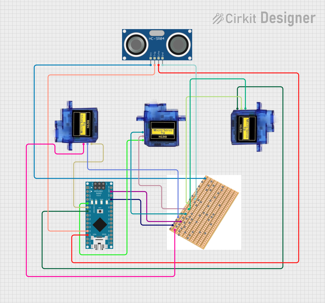
Arduino Nano-Controlled Ultrasonic Distance Measurement with Servo Feedback

Circuit Documentation
Summary
This circuit integrates an Arduino Nano microcontroller with three Micro servo 9G motors and an HC-SR04 Ultrasonic Sensor. The Arduino Nano serves as the central processing unit, controlling the servo motors via PWM signals and interfacing with the ultrasonic sensor for distance measurement. A vero board is used as a common platform for power distribution and ground connections.
Component List
Arduino Nano
- Microcontroller board based on the ATmega328P
- Offers a variety of digital and analog I/O pins
- Can be powered via USB or an external power supply
Micro servo 9G (x3)
- Small and lightweight servo motor
- Operates on +5V and controlled via a PWM signal
- Commonly used for simple mechanical movements in robotics and models
HC-SR04 Ultrasonic Sensor
- Ultrasonic distance measuring module
- Uses sonar to determine the distance to an object
- Features a trigger and echo pin for interfacing with a microcontroller
Vero Board
- A prototyping board used for circuit construction
- Provides a means to easily connect various components together
- Used here for power distribution and common ground connections
Wiring Details
Arduino Nano
- D2: Connected to the PWM pin of the first Micro servo 9G
- D3: Connected to the PWM pin of the second Micro servo 9G
- D4: Connected to the PWM pin of the third Micro servo 9G
- D9: Connected to the TRIG pin of the HC-SR04 Ultrasonic Sensor
- D10: Connected to the ECHO pin of the HC-SR04 Ultrasonic Sensor
- GND: Connected to the vero board for common ground
- 5V: Connected to the vero board for power distribution
Micro servo 9G (Servo 1)
- PWM: Connected to D2 on the Arduino Nano
- GND: Connected to the vero board for common ground
- +5V: Connected to the vero board for power
Micro servo 9G (Servo 2)
- PWM: Connected to D3 on the Arduino Nano
- GND: Connected to the vero board for common ground
- +5V: Connected to the vero board for power
Micro servo 9G (Servo 3)
- PWM: Connected to D4 on the Arduino Nano
- GND: Connected to the vero board for common ground
- +5V: Connected to the vero board for power
HC-SR04 Ultrasonic Sensor
- TRIG: Connected to D9 on the Arduino Nano
- ECHO: Connected to D10 on the Arduino Nano
- GND: Connected to the vero board for common ground
- VCC: Connected to the vero board for power
Vero Board
- Acts as a common point for ground and +5V power distribution to all components
Documented Code
void setup() {
  // put your setup code here, to run once:

}

void loop() {
  // put your main code here, to run repeatedly:

}
The provided code is a template with empty setup() and loop() functions, which are the standard structure for Arduino sketches. The setup() function is intended for code that runs once upon reset or power-up, such as pin mode configurations. The loop() function contains code that runs continuously, which would include the main logic for controlling the servo motors and reading data from the ultrasonic sensor. Specific implementation details would need to be added to these functions to control the hardware as intended.