ESP32-Controlled Water Management System with Solid State Relays and Sensor Monitoring
Circuit Documentation
Summary
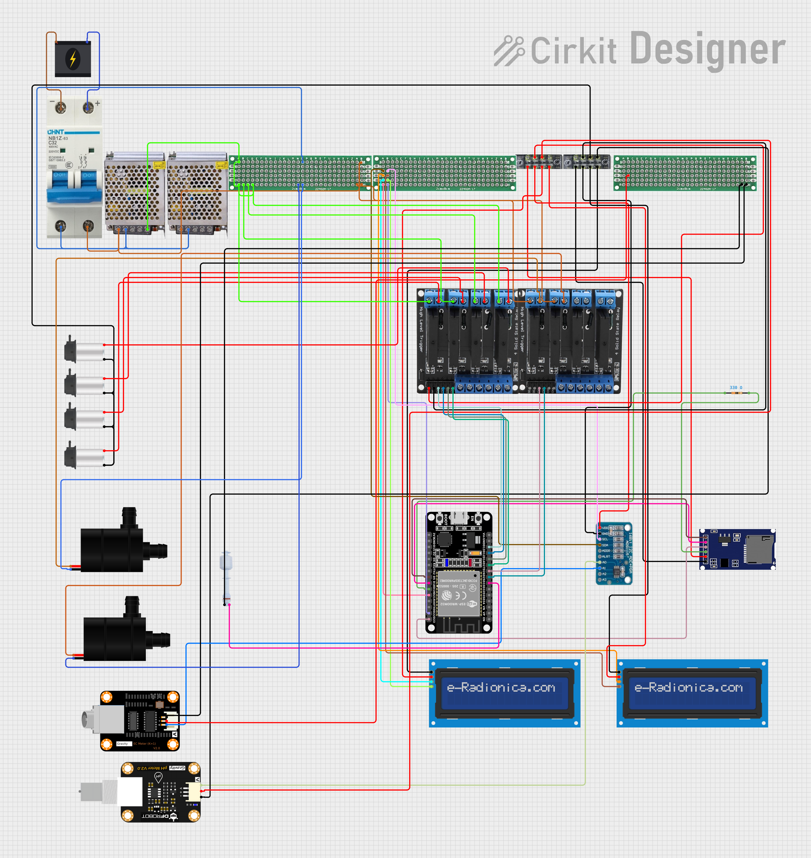
The circuit in question appears to be designed for controlling various pumps and sensors, likely for an automated system such as a hydroponic setup or an aquarium. It includes solid-state relays for controlling power to the pumps, an ESP32 microcontroller for logic control, sensors for monitoring pH and electrical conductivity (EC), and an LCD screen for displaying information. The circuit also includes a power supply, a circuit breaker for safety, and a terminal block for organizing connections.
Component List
Microcontroller
- ESP32 (30 pin): A microcontroller with Wi-Fi and Bluetooth capabilities, used for controlling the various components in the circuit.
Sensors
- Float Switch: Used to detect the presence or absence of liquid at a certain level.
- Modulo Sensor PH: A sensor for measuring the pH level of a solution.
- DFRobot EC Sensor: A sensor for measuring the electrical conductivity of a solution, which is related to the ionic content.
Actuators
- 4 Solid State Relay: Used to control high power devices such as pumps with a low power control signal from the ESP32.
- Water Pump: An electric pump for moving water.
- Peristaltic Pump: A type of pump used for precise dosing of liquids.
Power Components
- 240v Power Source: The main power source for the circuit.
- Circuit Breaker: A safety device to protect the circuit from overcurrent conditions.
- POWER SUPPLY 5V 5AMP: Converts 220V AC to 5V DC to power low voltage components.
Display
- LCD screen 16x2 I2C: A display for showing information to the user, interfaced via I2C.
Data Storage
- SDmodule: A module for reading from and writing to SD cards.
Miscellaneous
- ADS1115: A precision analog-to-digital converter (ADC) with I2C interface, used for reading analog sensor data.
- Resistor (330 Ohms): Used for current limiting or voltage division in the circuit.
- Terminal Block (04-01): A connector for joining multiple wires together.
- 2cmx8cm PCB: A printed circuit board used for mounting and interconnecting components.
Wiring Details
ESP32 (30 pin)
- Digital pins D33, D25, D26, D27, D14, D12, D13, D23, D22, D21, D19, D18, D5 are connected to various components for control signals.
- GND and Vin pins are used for power connections.
Float Switch
- Connected to the ESP32 for liquid level detection.
4 Solid State Relay
- Controlled by the ESP32 to switch pumps on and off.
- Powered by the 5V power supply.
Water Pump
- Powered by the solid-state relays, controlled by the ESP32.
Peristaltic Pump
- Multiple instances, each powered by the solid-state relays, controlled by the ESP32.
POWER SUPPLY 5V 5AMP
- Provides 5V DC power to the circuit from a 220V AC source.
ADS1115
- Reads analog values from the pH and EC sensors.
- Communicates with the ESP32 via I2C.
LCD screen 16x2 I2C
- Displays information, interfaced with the ESP32 via I2C.
SDmodule
- Interfaces with the ESP32 for data logging to an SD card.
Terminal Block (04-01)
- Organizes various power and signal connections.
Resistor (330 Ohms)
- Likely used in conjunction with the SDmodule for signal integrity.
Documented Code
No code was provided in the input. The ESP32 would typically be programmed to read sensor data, control the solid-state relays based on sensor inputs or timing, log data to the SD card, and display information on the LCD screen. The code would also handle communication protocols such as I2C for interfacing with the LCD and the ADC.