Arduino UNO Controlled RGB LED Circuit with Pushbutton Interaction
Circuit Documentation
Summary of the Circuit
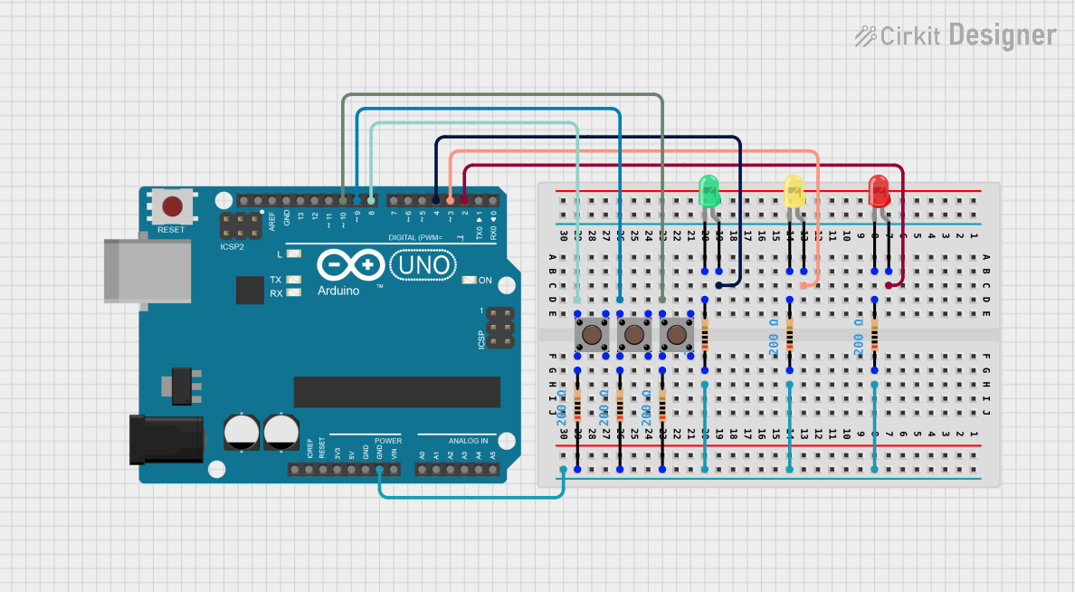
This circuit is designed around an Arduino UNO microcontroller and includes a variety of components such as LEDs, resistors, and pushbuttons. The circuit appears to be set up for basic input/output operations with the Arduino UNO controlling the LEDs and reading the state of the pushbuttons. Each LED is connected to a digital output pin on the Arduino through a current-limiting resistor. The pushbuttons are connected to other digital pins and are likely used to trigger events or actions when pressed.
Component List
Arduino UNO
- Microcontroller board based on the ATmega328P
- It has 14 digital input/output pins, 6 analog inputs, a 16 MHz quartz crystal, a USB connection, a power jack, an ICSP header, and a reset button.
LED: Two Pin (red)
- A basic red LED for indicating status or for simple display purposes.
LED: Two Pin (yellow)
- A basic yellow LED similar in function to the red LED, used for status indication.
LED: Two Pin (green)
- A basic green LED, also for status indication or display.
Resistor (200 Ohms)
- A resistor with a resistance of 200 Ohms, likely used for current limiting to protect the LEDs.
Pushbutton
- A simple pushbutton switch that can be used to input a signal to the Arduino when pressed.
Wiring Details
Arduino UNO
- Digital Pin 2 connected to the anode of the red LED.
- Digital Pin 3 connected to the anode of the yellow LED.
- Digital Pin 4 connected to the anode of the green LED.
- Digital Pin 8 connected to one side of a pushbutton.
- Digital Pin 9 connected to one side of another pushbutton.
- Digital Pin 10 connected to one side of a third pushbutton.
- Ground (GND) connected to one side of all resistors.
LED: Two Pin (red)
- Anode connected to Arduino UNO Digital Pin 2.
- Cathode connected to one side of a 200 Ohm resistor.
LED: Two Pin (yellow)
- Anode connected to Arduino UNO Digital Pin 3.
- Cathode connected to one side of a 200 Ohm resistor.
LED: Two Pin (green)
- Anode connected to Arduino UNO Digital Pin 4.
- Cathode connected to one side of a 200 Ohm resistor.
Resistor (200 Ohms)
- One side connected to the cathode of an LED.
- The other side connected to the Ground (GND) of the Arduino UNO.
Pushbutton
- One side (Pin 1 (in)) connected to an Arduino UNO digital pin (D8, D9, or D10).
- The other side (Pin 2 (in)) connected to one side of a 200 Ohm resistor.
Documented Code
Arduino UNO Code (sketch.ino)
void setup() {
  // put your setup code here, to run once:

}

void loop() {
  // put your main code here, to run repeatedly:

}
This code is a template and does not contain any specific functionality. It consists of two functions: setup(), which runs once when the microcontroller is reset or powered on, and loop(), which runs continuously as long as the microcontroller is powered. To control the LEDs and read the pushbuttons, code will need to be added to these functions to initialize the pins as inputs or outputs and to perform the desired logic operations.