
Arduino UNO Line Following Robot with IR Sensors and L298N Motor Driver
View and Edit Project In Cirkit Designer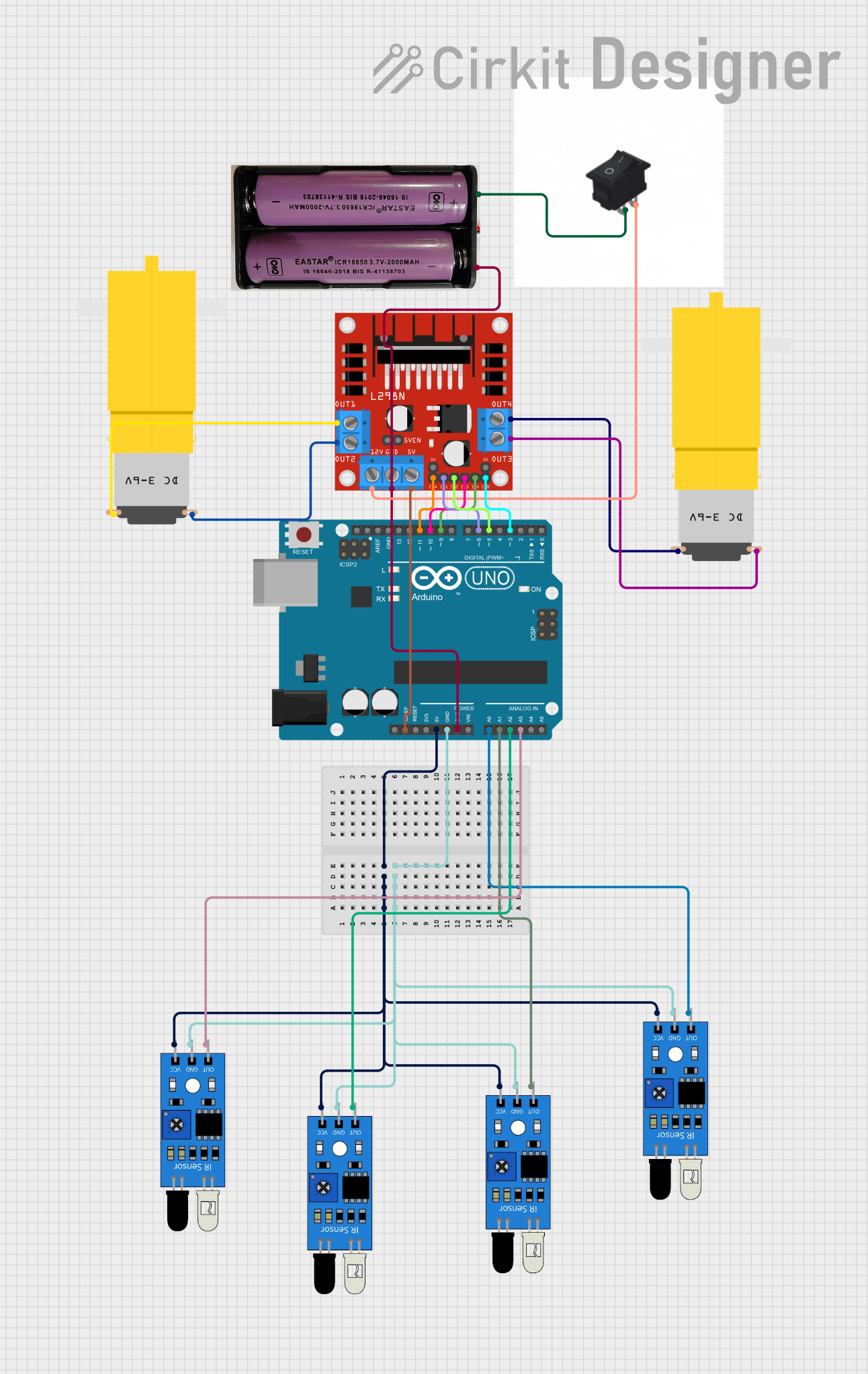
Circuit Documentation
Summary
This document provides a detailed overview of a line-following robot circuit. The circuit consists of an Arduino UNO microcontroller, an L298N DC motor driver, multiple IR sensors, two hobby motors, a rocker switch, and a 7.4V battery. The Arduino UNO reads the IR sensor values to determine the position of the line and adjusts the motor speeds accordingly using a PID control algorithm.
Component List
Arduino UNO
- Description: Microcontroller board based on the ATmega328P.
- Pins: UNUSED, IOREF, Reset, 3.3V, 5V, GND, Vin, A0, A1, A2, A3, A4, A5, SCL, SDA, AREF, D13, D12, D11, D10, D9, D8, D7, D6, D5, D4, D3, D2, D1, D0
L298N DC Motor Driver
- Description: Dual H-Bridge motor driver module.
- Pins: OUT1, OUT2, 12V, GND, 5V, OUT3, OUT4, 5V-ENA-JMP-I, 5V-ENA-JMP-O, +5V-J1, +5V-J2, ENA, IN1, IN2, IN3, IN4, ENB
7.4V Battery
- Description: Power source for the circuit.
- Pins: +, -
IR Sensor
- Description: Infrared sensor for line detection.
- Pins: out, gnd, vcc
Motor (Hobby)
- Description: DC motor with gearbox.
- Pins: vcc, GND
Rocker Switch
- Description: On/Off switch.
- Pins: 1, 2
Wiring Details
Arduino UNO
- 5V: Connected to
vccof all IR sensors. - GND: Connected to
gndof all IR sensors and the GND of the L298N DC motor driver. - IOREF: Connected to
5Vof the L298N DC motor driver. - A0: Connected to
outof the first IR sensor. - A1: Connected to
outof the second IR sensor. - A2: Connected to
outof the third IR sensor. - A3: Connected to
outof the fourth IR sensor. - D11: Connected to
ENAof the L298N DC motor driver. - D10: Connected to
IN3of the L298N DC motor driver. - D9: Connected to
IN4of the L298N DC motor driver. - D6: Connected to
IN1of the L298N DC motor driver. - D5: Connected to
IN2of the L298N DC motor driver. - D3: Connected to
ENBof the L298N DC motor driver.
L298N DC Motor Driver
- 5V: Connected to
IOREFof the Arduino UNO. - GND: Connected to
-of the 7.4V battery and GND of the Arduino UNO. - 12V: Connected to pin
1of the rocker switch. - ENA: Connected to
D11of the Arduino UNO. - IN3: Connected to
D10of the Arduino UNO. - IN4: Connected to
D9of the Arduino UNO. - IN1: Connected to
D6of the Arduino UNO. - IN2: Connected to
D5of the Arduino UNO. - ENB: Connected to
D3of the Arduino UNO. - OUT1: Connected to
vccof the first hobby motor. - OUT2: Connected to
GNDof the first hobby motor. - OUT3: Connected to
GNDof the second hobby motor. - OUT4: Connected to
vccof the second hobby motor.
7.4V Battery
- +: Connected to pin
2of the rocker switch. - -: Connected to
GNDof the L298N DC motor driver and Arduino UNO.
IR Sensors
- vcc: Connected to
5Vof the Arduino UNO. - gnd: Connected to
GNDof the Arduino UNO. - out: Connected to
A0,A1,A2, andA3of the Arduino UNO respectively.
Hobby Motors
- vcc: Connected to
OUT1andOUT4of the L298N DC motor driver. - GND: Connected to
OUT2andOUT3of the L298N DC motor driver.
Rocker Switch
- 1: Connected to
12Vof the L298N DC motor driver. - 2: Connected to
+of the 7.4V battery.
Code Documentation
// Define sensor pins
#define LEFT_SENSOR A0
#define LEFT_CENTER_SENSOR A1
#define RIGHT_CENTER_SENSOR A2
#define RIGHT_SENSOR A3

// Define motor pins
#define LEFT_MOTOR_FWD 5
#define LEFT_MOTOR_BWD 6
#define RIGHT_MOTOR_FWD 9
#define RIGHT_MOTOR_BWD 10

// PID control variables
float Kp = 1.0;     // Proportional gain
float Ki = 0.0;     // Integral gain
float Kd = 0.5;     // Derivative gain
float error, lastError = 0, integral = 0, derivative = 0;
int baseSpeed = 150; // Base motor speed (adjust based on testing)
int maxSpeed = 255;  // Maximum motor speed

// Infrared sensor values
int left, leftCenter, rightCenter, right;

void setup() {
  // Set motor pins as outputs
  pinMode(LEFT_MOTOR_FWD, OUTPUT);
  pinMode(LEFT_MOTOR_BWD, OUTPUT);
  pinMode(RIGHT_MOTOR_FWD, OUTPUT);
  pinMode(RIGHT_MOTOR_BWD, OUTPUT);

  // Set sensor pins as inputs
  pinMode(LEFT_SENSOR, INPUT);
  pinMode(LEFT_CENTER_SENSOR, INPUT);
  pinMode(RIGHT_CENTER_SENSOR, INPUT);
  pinMode(RIGHT_SENSOR, INPUT);

  // Start serial monitor for debugging (optional)
  Serial.begin(9600);
}

void loop() {
  readSensors();
  followLine();
}

// Function to read IR sensors
void readSensors() {
  left = analogRead(LEFT_SENSOR);
  leftCenter = analogRead(LEFT_CENTER_SENSOR);
  rightCenter = analogRead(RIGHT_CENTER_SENSOR);
  right = analogRead(RIGHT_SENSOR);
}

// Function to follow the line using PID control
void followLine() {
  error = calculateError();
  integral += error;
  derivative = error - lastError;

  // PID calculation
  int adjust = Kp * error + Ki * integral + Kd * derivative;
  int leftMotorSpeed = constrain(baseSpeed + adjust, 0, maxSpeed);
  int rightMotorSpeed = constrain(baseSpeed - adjust, 0, maxSpeed);

  // Set motor speeds based on PID adjustment
  setMotorSpeeds(leftMotorSpeed, rightMotorSpeed);

  lastError = error;  // Update lastError for the next loop
}

// Function to calculate error based on sensor values
float calculateError() {
  if (left && !leftCenter && !rightCenter && right) return 0;       // Centered
  if (left && leftCenter && !rightCenter && !right) return -2;      // Slightly left
  if (!left && !leftCenter && rightCenter && right) return 2;       // Slightly right
  if (left && leftCenter && rightCenter && !right) return -3;       // Far left
  if (!left && leftCenter && rightCenter && right) return 3;        // Far right
  return 0;                                                         // Default to center
}

// Function to control motor speeds based on PID adjustments
void setMotorSpeeds(int leftSpeed, int rightSpeed) {
  if (leftSpeed >= 0) {
    analogWrite(LEFT_MOTOR_FWD, leftSpeed);
    digitalWrite(LEFT_MOTOR_BWD, LOW);
  } else {
    analogWrite(LEFT_MOTOR_BWD, -leftSpeed);
    digitalWrite(LEFT_MOTOR_FWD, LOW);
  }

  if (rightSpeed >= 0) {
    analogWrite(RIGHT_MOTOR_FWD, rightSpeed);
    digitalWrite(RIGHT_MOTOR_BWD, LOW);
  } else {
    analogWrite(RIGHT_MOTOR_BWD, -rightSpeed);
    digitalWrite(RIGHT_MOTOR_FWD, LOW);
  }
}
This code defines the pins for the IR sensors and motors, sets up the pins in the setup() function, and continuously reads the sensor values and adjusts the motor speeds in the loop() function using a PID