
Arduino UNO R4 WiFi Controlled LCD Display with DHT11 Sensor Integration
View and Edit Project In Cirkit Designer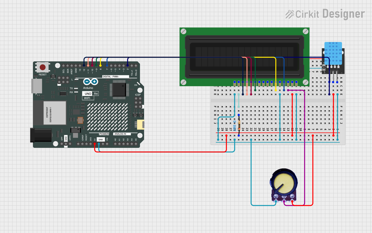
Circuit Documentation
Summary of the Circuit
This circuit integrates an Arduino UNO R4 WiFi with a DHT11 temperature and humidity sensor, an LCD display, a potentiometer for contrast adjustment, and a resistor for current limiting purposes. The Arduino serves as the central processing unit, interfacing with the DHT11 sensor to read environmental data and displaying this information on the LCD. The potentiometer is used to adjust the contrast of the LCD, and the resistor is connected to the backlight of the LCD to limit the current.
Component List
Arduino UNO R4 WiFi
- Description: A microcontroller board based on the ATmega328P with WiFi capabilities.
- Pins: OFF, GND, VRTC, IIC0_SCL, IIC0_SDA, 3V3, GPIO 41, GPIO 0, GPIO 42, GPIO 43, GPIO 44, BOOT, IOREF, RESET, 5V, VIN, A0, A1, A2, A3, A4, A5, RSPCKA, CIPO, COPI, D0/RX, D1/TX, D2, D3, D4, D5, D6, D7, D8, D9, D10, D11, D12, D13, AREF, SDA, SCL
LCD Display (16 pin)
- Description: A 16-pin liquid crystal display for showing alphanumeric characters.
- Pins: VSS, VDD, VO, RS, R_W, E, DB0, DB1, DB2, DB3, DB4, DB5, DB6, DB7, A, K
DHT11
- Description: A basic, ultra low-cost digital temperature and humidity sensor.
- Pins: 5V, S, GND
Potentiometer
- Description: A three-terminal resistor with a rotating contact that forms an adjustable voltage divider.
- Pins: GND, Output, VCC
Resistor
- Description: A passive two-terminal electrical component that implements electrical resistance as a circuit element.
- Pins: pin1, pin2
- Properties: Resistance - 200 Ohms
Wiring Details
Arduino UNO R4 WiFi
- GND connected to common ground.
- 5V connected to the VCC of the DHT11 and the VDD of the LCD Display.
- D2 connected to the 5V pin of the DHT11.
- D7 connected to the RS pin of the LCD Display.
- D8 connected to the E pin of the LCD Display.
- D9 connected to the DB4 pin of the LCD Display.
- D10 connected to the DB5 pin of the LCD Display.
- D11 connected to the DB6 pin of the LCD Display.
- D12 connected to the DB7 pin of the LCD Display.
LCD Display (16 pin)
- VSS, R_W, and K connected to common ground.
- VDD connected to 5V from the Arduino.
- VO connected to the Output of the Potentiometer for contrast adjustment.
- RS, E, DB4, DB5, DB6, DB7 connected to the corresponding pins on the Arduino.
- A connected to one pin of the Resistor.
DHT11
- 5V connected to the D2 pin of the Arduino.
- S connected to one pin of the Resistor.
- GND connected to common ground.
Potentiometer
- GND connected to common ground.
- Output connected to the VO pin of the LCD Display for contrast adjustment.
- VCC connected to 5V from the Arduino.
Resistor
- One pin connected to the A pin of the LCD Display.
- The other pin connected to the S pin of the DHT11.
Documented Code
Arduino UNO R4 WiFi Code (sketch.ino)
void setup() {
  // put your setup code here, to run once:

}

void loop() {
  // put your main code here, to run repeatedly:

}
Additional Notes (documentation.txt)
No additional code documentation provided.