
Circuit Documentation
Summary of the Circuit
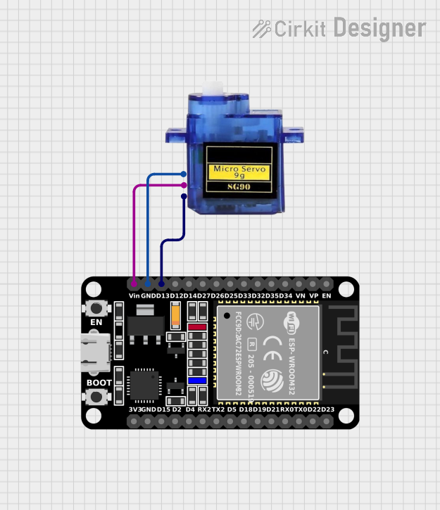
This circuit consists of an ESP32 microcontroller and a Micro servo 9G. The ESP32 is a versatile microcontroller with Wi-Fi and Bluetooth capabilities, which is commonly used in various IoT applications. The Micro servo 9G is a small and lightweight servo motor suitable for projects that require simple motion tasks.
The ESP32 is responsible for controlling the servo motor by sending PWM (Pulse Width Modulation) signals to the servo's control pin. The ground and power supply pins of the servo are connected to the corresponding pins on the ESP32 to complete the circuit.
Component List
ESP32 (30 pin)
- Description: A 30-pin microcontroller with Wi-Fi and Bluetooth capabilities.
- Pins: EN, VP, VN, D34, D35, D32, D33, D25, D26, D27, D14, D12, D13, GND, Vin, D23, D22, TX0, RX0, D21, D19, D18, D5, TX2, RX2, D4, D2, D15, 3V3
- Purpose: Acts as the central processing unit of the circuit, controlling the servo motor and potentially communicating with other devices or networks.
Micro servo 9G
- Description: A compact and lightweight servo motor for basic motion control.
- Pins: GND, +5V, PWM
- Purpose: Executes physical movements as instructed by the PWM signals from the ESP32.
Wiring Details
ESP32 (30 pin)
- D13: Connected to the PWM pin of the Micro servo 9G for sending control signals.
- GND: Connected to the GND pin of the Micro servo 9G to establish a common ground.
- Vin: Connected to the +5V pin of the Micro servo 9G to provide power to the servo.
Micro servo 9G
- PWM: Receives PWM signals from the D13 pin of the ESP32 for operation.
- GND: Connected to the GND pin of the ESP32 to complete the circuit's ground path.
- +5V: Receives power from the Vin pin of the ESP32.
Documented Code
No code has been provided for the microcontroller. To operate the servo motor, code should be written and uploaded to the ESP32 that generates PWM signals on the D13 pin. The code should define the pulse width corresponding to the desired position of the servo motor.