Cirkit Designer
Your all-in-one circuit design IDE
Home /
Project Documentation
Arduino-Controlled Dual DC Motor Driver with IR Sensors
Circuit Documentation
Summary
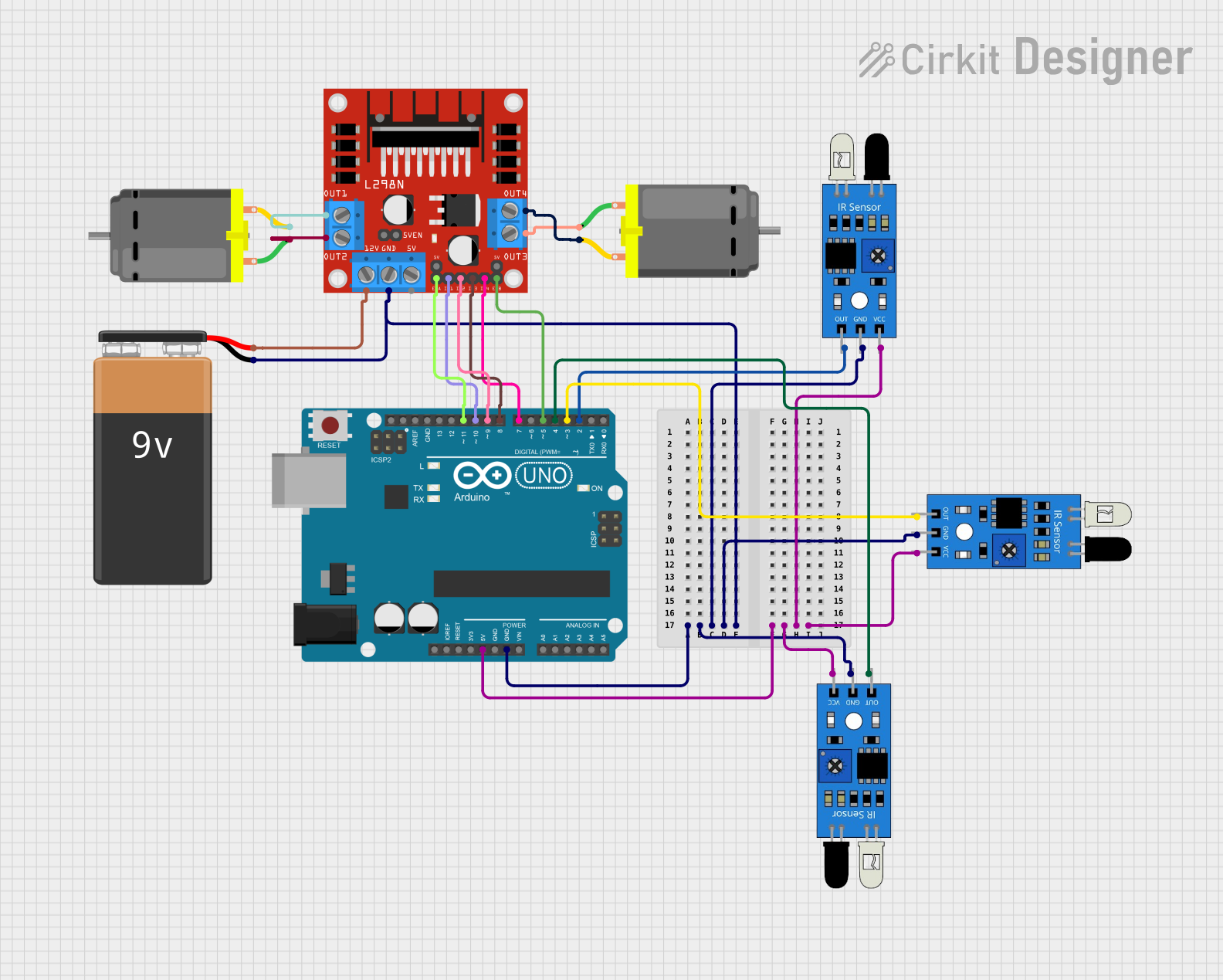
This circuit is designed to interface an Arduino UNO with multiple IR sensors and control two DC motors through an L298N DC motor driver. The IR sensors are powered by the 5V output from the Arduino and their outputs are connected to digital pins on the Arduino for sensing. The L298N motor driver receives control signals from the Arduino to drive the motors and is powered by a 9V battery. The motors are connected to the output of the L298N driver.
Component List
Arduino UNO
- Microcontroller board based on the ATmega328P
- It has 14 digital input/output pins, 6 analog inputs, a 16 MHz quartz crystal, a USB connection, a power jack, an ICSP header, and a reset button.
IR Sensors
- Infrared sensors used for object detection
- Each sensor has an output pin, a ground pin, and a VCC pin for power.
L298N DC Motor Driver
- A module used for controlling up to two DC motors
- It has pins for motor outputs, power supply, and control inputs.
DC Motors
- Two motors that convert electrical energy into mechanical motion
- Each motor has two pins for connecting to the motor driver.
9V Battery
- Provides power to the L298N motor driver
- It has a positive and a negative terminal.
Wiring Details
Arduino UNO
- 5V pin provides power to the VCC pins of all IR sensors.
- GND pin is connected to the ground pins of all IR sensors and the GND pin of the L298N motor driver.
- Digital pins D2, D3, D4, D5, D7, D8, D9, D10, and D11 are used to interface with the L298N motor driver and IR sensors.
IR Sensors
- VCC pins connected to the 5V output from the Arduino UNO.
- GND pins connected to the ground (GND) on the Arduino UNO.
- Output pins connected to digital pins D2, D3, and D4 on the Arduino UNO.
L298N DC Motor Driver
- GND pin connected to the negative terminal of the 9V battery and GND on the Arduino UNO.
- 12V pin connected to the positive terminal of the 9V battery.
- ENA and ENB pins connected to digital pins D11 and D5 on the Arduino UNO, respectively.
- IN1, IN2, IN3, and IN4 pins connected to digital pins D10, D9, D8, and D7 on the Arduino UNO, respectively.
- OUT1, OUT2, OUT3, and OUT4 pins connected to the respective pins of the two DC motors.
DC Motors
- Each motor is connected to two output pins on the L298N motor driver.
9V Battery
- Positive terminal connected to the 12V pin on the L298N motor driver.
- Negative terminal connected to the GND pin on the L298N motor driver.
Documented Code
Arduino UNO Code (sketch.ino)
void setup() {
  // put your setup code here, to run once:

}

void loop() {
  // put your main code here, to run repeatedly:

}
Additional Notes (documentation.txt)
No additional code documentation was provided.