
NodeMCU ESP8266 with Multiple IR Sensors and LDR-Controlled LEDs
View and Edit Project In Cirkit Designer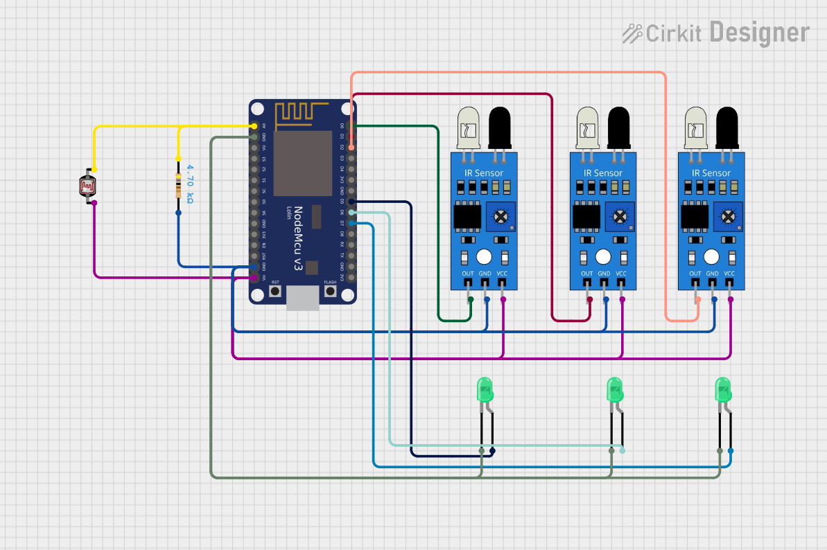
Circuit Documentation
Summary of the Circuit
The circuit in question appears to be designed around the NodeMCU V3 ESP8266 microcontroller and includes several peripherals: three IR sensors, three green LEDs, a photocell (LDR), and a resistor. The NodeMCU is responsible for interfacing with the IR sensors and controlling the LEDs based on the inputs from these sensors. The photocell is connected to an analog input for light sensing, and the resistor is likely used for setting up a voltage divider or current-limiting configuration.
Component List
NodeMCU V3 ESP8266
- Description: A microcontroller board based on the ESP8266 chip, featuring Wi-Fi capabilities and a variety of digital and analog pins.
- Pins: A0, GND, VU, S3, S2, S1, SC, S0, SK, 3V3, EN, RST, Vin, D0, D1, D2, D3, D4, D5, D6, D7, D8, RX, TX
IR Sensor
- Description: An infrared sensor capable of detecting obstacles or measuring distances.
- Pins: out, gnd, vcc
LED: Two Pin (green)
- Description: A basic green LED with an anode and cathode for emitting light.
- Pins: cathode, anode
Resistor
- Description: A passive component used to limit current or divide voltage.
- Value: 4700 Ohms
Photocell (LDR)
- Description: A light-dependent resistor whose resistance changes based on the intensity of light it is exposed to.
- Pins: pin 0, pin 1
Wiring Details
NodeMCU V3 ESP8266
- A0 connected to Photocell (LDR) pin 1 and Resistor pin1
- GND connected to all LED cathodes and IR sensor gnd pins
- Vin connected to all IR sensor vcc pins and Photocell (LDR) pin 0
- D0 connected to IR sensor out
- D1 connected to IR sensor out
- D2 connected to IR sensor out
- D5 connected to LED anode
- D6 connected to LED anode
- D7 connected to LED anode
IR Sensor
- out connected to NodeMCU pins D0, D1, D2 (one sensor per pin)
- gnd connected to NodeMCU GND
- vcc connected to NodeMCU Vin
LED: Two Pin (green)
- cathode connected to NodeMCU GND
- anode connected to NodeMCU pins D5, D6, D7 (one LED per pin)
Resistor
- pin1 connected to NodeMCU A0
- pin2 connected to NodeMCU GND
Photocell (LDR)
- pin 0 connected to NodeMCU Vin
- pin 1 connected to NodeMCU A0
Documented Code
No code has been provided for the microcontroller. The expected behavior based on the hardware connections would involve reading the analog value from the photocell via the A0 pin, detecting the presence of objects with the IR sensors connected to the D0, D1, and D2 pins, and controlling the state of the LEDs connected to the D5, D6, and D7 pins. Without the actual code, we cannot provide further details on the logic or functionality implemented in the microcontroller.