Cirkit Designer
Your all-in-one circuit design IDE
Home /
Project Documentation
Arduino UNO R4 WiFi-Controlled Environmental Monitoring and Watering System

Circuit Documentation
Summary
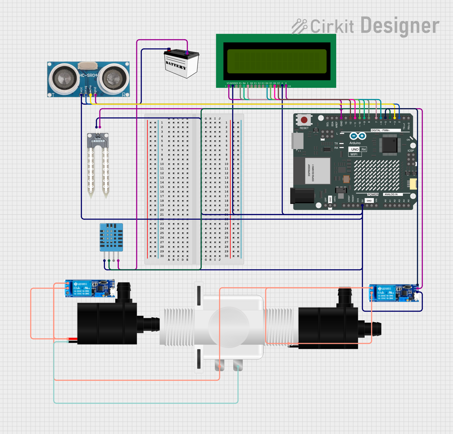
This circuit is designed to interface various sensors and actuators with an Arduino UNO R4 WiFi microcontroller. The circuit includes an ultrasonic sensor, a DHT11 humidity and temperature sensor, a water sensor, two water pumps, two relay modules, a plastic solenoid valve, a 16X2 LCD display, and a 12V battery. The Arduino UNO R4 WiFi is used as the central processing unit to read sensor data, control the water pumps via the relay modules, and display information on the LCD. The 12V battery provides power to the circuit.
Component List
Ultrasonic Sensor
- Used for measuring distance via ultrasonic waves.
- Pins: +VCC, Trigger, Echo, GND
DHT11 Humidity and Temperature Sensor
- Measures ambient humidity and temperature.
- Pins: VDD, DATA, NULL, GND
Water Sensor
- Detects the presence of water.
- Pins: -, +
Water Pump
- Pumps water when activated.
- Pins: VCC, GND
Relay Module 5V-30V
- Controls high power devices using low power signals.
- Pins: Common Contact, Normally Open, Normally Closed, Trigger, V-, V+
Plastic Solenoid Valve
- Controls the flow of liquid when electrically actuated.
- Pins: Pin1, Pin2
Arduino UNO R4 WiFi
- Microcontroller board with WiFi capability.
- Pins: Various GPIO, Power, and Analog pins
16X2 LCD
- Displays text information.
- Pins: VSS, VDD, V0, RS, RW, E, D0-D7, A, K
12V Battery (Small Size)
- Provides power to the circuit.
- Pins: VCC, GND
Wiring Details
Ultrasonic Sensor
- +VCC connected to 5V power supply.
- Trigger connected to Arduino Pin D2.
- Echo connected to Arduino Pin D3.
- GND connected to ground.
DHT11 Humidity and Temperature Sensor
- VDD connected to 5V power supply.
- DATA connected to Arduino Pin D4.
- GND connected to ground.
Water Sensor
- connected to 5V power supply.
- connected to ground.
Water Pump
- VCC connected to Normally Open pin of Relay Module.
- GND connected to ground.
Relay Module 5V-30V
- V+ connected to 5V power supply.
- V- connected to ground.
- Trigger connected to Arduino Pin D5.
- Common Contact connected to power supply.
- Normally Open connected to Water Pump VCC.
Plastic Solenoid Valve
- Pin1 connected to Normally Open pin of Relay Module.
- Pin2 connected to ground.
16X2 LCD
- VDD connected to 5V power supply.
- VSS connected to ground.
- RS connected to Arduino Pin D8.
- RW connected to Arduino Pin D9.
- E connected to Arduino Pin D7.
- D4-D7 connected to Arduino Pins D6, D10, D11, D12 respectively.
- A connected to 5V power supply.
- K connected to ground.
12V Battery (Small Size)
- VCC connected to 5V power supply.
- GND connected to ground.
Documented Code
Arduino UNO R4 WiFi Code (sketch.ino)
void setup() {
  // put your setup code here, to run once:

}

void loop() {
  // put your main code here, to run repeatedly:

}
Additional Notes
- The provided code is a template and does not contain any functional code. It needs to be populated with the logic to read sensors, control actuators, and display data on the LCD.
- The
setup()function is used for initializing settings, and theloop()function runs continuously, allowing the microcontroller to perform operations based on sensor inputs and desired outputs.