
Raspberry Pi Pico W Weather Station with BMP280 and I2C LCD Display
View and Edit Project In Cirkit Designer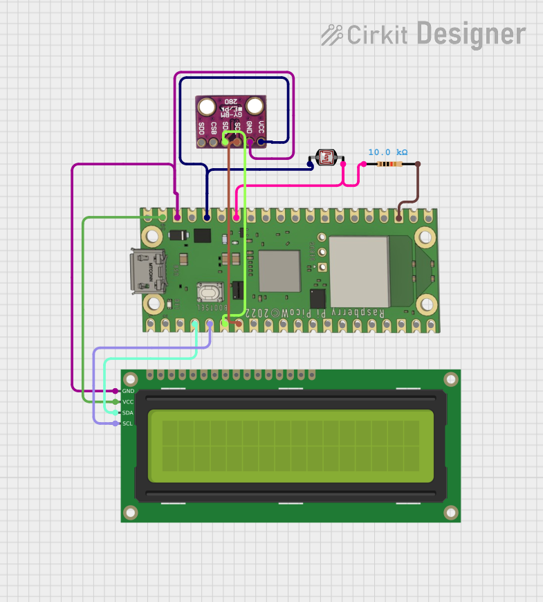
Circuit Documentation
Summary
This document provides a detailed overview of a circuit that includes a Raspberry Pi Pico W microcontroller, a BMP280 sensor, a 16x2 I2C LCD, a Photocell (LDR), and a Resistor. The circuit is designed to interface these components for various sensing and display purposes.
Component List
Raspberry Pi Pico W
- Description: A low-cost, high-performance microcontroller board with flexible digital interfaces.
- Pins: VBUS, VSYS, GP16, GP17, GND, GP18, GP19, GP20, GP21, GP22, RUN, GP26, GP27, GP28, ADC_VREF, 3V3 OUT, 3V3_EN, GP0, GP1, GP2, GP3, GP4, GP5, GP6, GP7, GP15, GP14, GP13, GP12, GP11, GP10, GP9, GP8
BMP280
- Description: A barometric pressure sensor that can measure atmospheric pressure and temperature.
- Pins: SDO, CSB, SDA, SCL, GND, VCC
16x2 I2C LCD
- Description: A 16x2 character LCD display with I2C interface.
- Pins: GND, VCC, SDA, SCL
Photocell (LDR)
- Description: A light-dependent resistor that changes its resistance based on the light intensity.
- Pins: pin 0, pin 1
Resistor
- Description: A 10k Ohm resistor used to limit current or divide voltage.
- Pins: pin1, pin2
- Properties:
- Resistance: 10,000 Ohms
Wiring Details
Raspberry Pi Pico W
- VSYS is connected to VCC of the 16x2 I2C LCD.
- GND is connected to pin2 of the Resistor.
- GP28 is connected to pin 1 of the Photocell (LDR) and pin1 of the Resistor.
- 3V3 OUT is connected to VCC of the BMP280 and pin 0 of the Photocell (LDR).
- GND is connected to GND of the BMP280 and GND of the 16x2 I2C LCD.
- GP2 is connected to SDA of the 16x2 I2C LCD.
- GP3 is connected to SCL of the 16x2 I2C LCD.
- GP4 is connected to SDA of the BMP280.
- GP5 is connected to SCL of the BMP280.
BMP280
- VCC is connected to 3V3 OUT of the Raspberry Pi Pico W.
- GND is connected to GND of the Raspberry Pi Pico W.
- SDA is connected to GP4 of the Raspberry Pi Pico W.
- SCL is connected to GP5 of the Raspberry Pi Pico W.
16x2 I2C LCD
- VCC is connected to VSYS of the Raspberry Pi Pico W.
- GND is connected to GND of the Raspberry Pi Pico W.
- SDA is connected to GP2 of the Raspberry Pi Pico W.
- SCL is connected to GP3 of the Raspberry Pi Pico W.
Photocell (LDR)
- pin 0 is connected to 3V3 OUT of the Raspberry Pi Pico W.
- pin 1 is connected to GP28 of the Raspberry Pi Pico W and pin1 of the Resistor.
Resistor
- pin1 is connected to pin 1 of the Photocell (LDR) and GP28 of the Raspberry Pi Pico W.
- pin2 is connected to GND of the Raspberry Pi Pico W.
Code
No code is provided for this circuit.
This document provides a comprehensive overview of the circuit, including a summary, component list, wiring details, and code section. Each component is described in detail, and the wiring connections are clearly outlined to ensure proper assembly and functionality.