
Arduino-Based Temperature Monitoring System with RGB LED Feedback and I2C LCD Display
View and Edit Project In Cirkit Designer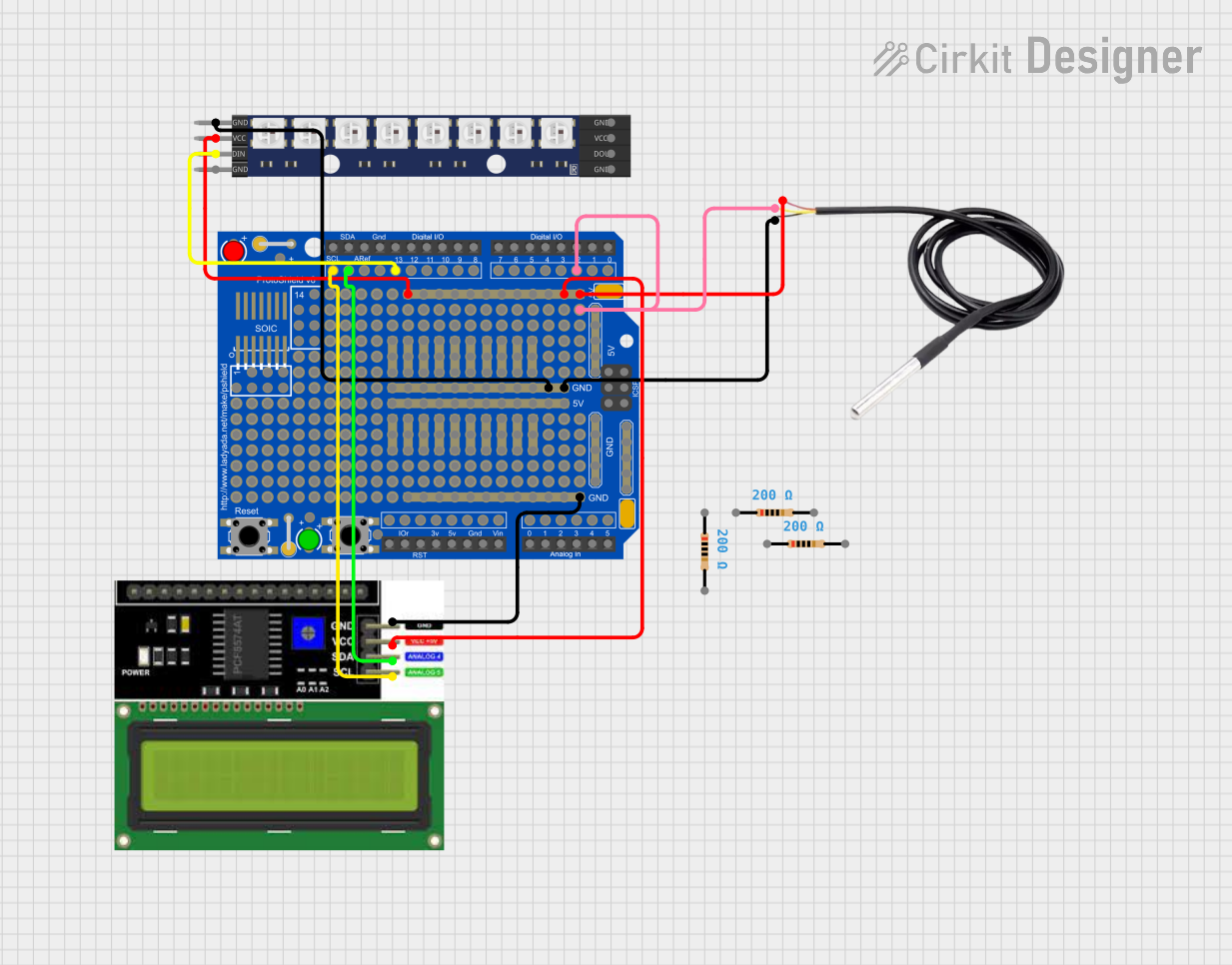
Circuit Documentation
Summary
This circuit is designed to interface an Adafruit Proto Shield R3 with a DS18B20 temperature sensor, a WS2812 RGB LED matrix, and an LCD I2C display. The circuit is powered by a +5V supply and includes ground connections to all components. The temperature sensor's signal is connected to a digital pin on the Proto Shield for temperature readings. The LED matrix is controlled by another digital pin, and the LCD display communicates over the I2C protocol using the SCL and SDA lines. The circuit includes embedded code to control the LEDs and display temperature readings on the LCD.
Component List
- Adafruit Proto Shield R3: A prototyping shield designed to sit on top of an Arduino Uno or similar boards, providing easy access to its pins for quick prototyping.
- DS18B20: A digital temperature sensor that provides 9-bit to 12-bit Celsius temperature measurements.
- WS2812 RGB LED matrix 1x8: A chainable strip of 8 RGB LEDs, each individually addressable for a variety of color effects.
- LCD I2C Display: A liquid crystal display that communicates over the I2C bus, capable of displaying text and numbers.
- Resistor (200 Ohms): Three resistors with a resistance of 200 Ohms each, possibly used for current limiting or pull-up/pull-down resistors in the circuit.
Wiring Details
Adafruit Proto Shield R3
- GND: Connected to the ground pins of the DS18B20, WS2812 RGB LED matrix, and LCD I2C Display.
- +5V: Powers the DS18B20, WS2812 RGB LED matrix, and LCD I2C Display.
- D2: Digital input connected to the signal pin of the DS18B20 temperature sensor.
- D13: Digital output connected to the DIN pin of the WS2812 RGB LED matrix.
- SCL: I2C clock line connected to the SCL pin of the LCD I2C Display.
- SDA: I2C data line connected to the SDA pin of the LCD I2C Display.
DS18B20
- signal: Connected to the D2 pin on the Adafruit Proto Shield R3.
- GND: Connected to the ground (GND) on the Adafruit Proto Shield R3.
- vcc: Powered by the +5V pin on the Adafruit Proto Shield R3.
WS2812 RGB LED matrix 1x8
- VCC: Powered by the +5V pin on the Adafruit Proto Shield R3.
- GND: Connected to the ground (GND) on the Adafruit Proto Shield R3.
- DIN: Data input connected to the D13 pin on the Adafruit Proto Shield R3.
LCD I2C Display
- GND: Connected to the ground (GND) on the Adafruit Proto Shield R3.
- VCC: Powered by the +5V pin on the Adafruit Proto Shield R3.
- SDA: I2C data line connected to the SDA pin on the Adafruit Proto Shield R3.
- SCL: I2C clock line connected to the SCL pin on the Adafruit Proto Shield R3.
Resistor (200 Ohms)
- pin1: Wiring details not provided.
- pin2: Wiring details not provided.
Documented Code
#include <Wire.h>
#include <LiquidCrystal_I2C.h>
#include <Adafruit_NeoPixel.h>
#include <OneWire.h>
#include <DallasTemperature.h>

// Pin definitions
#define LED_GREEN 6
#define LED_RED 7
#define TEMP_SENSOR_PIN 2
#define LED_MATRIX_PIN 13

// LED matrix setup
Adafruit_NeoPixel strip = Adafruit_NeoPixel(8, LED_MATRIX_PIN, NEO_GRB + NEO_KHZ800);

// LCD setup
LiquidCrystal_I2C lcd(0x27, 16, 2);

// Temperature sensor setup
OneWire oneWire(TEMP_SENSOR_PIN);
DallasTemperature sensors(&oneWire);

// Temperature threshold for good/bad condition
const float TEMP_THRESHOLD = 25.0; // Example threshold, adjust as needed

void setup() {
  // Initialize serial communication
  Serial.begin(9600);

  // Initialize LED pins
  pinMode(LED_GREEN, OUTPUT);
  pinMode(LED_RED, OUTPUT);

  // Initialize LED matrix
  strip.begin();
  strip.show();

  // Initialize LCD
  lcd.init();
  lcd.backlight();

  // Initialize temperature sensor
  sensors.begin();
}

void loop() {
  // Update LED matrix with random colors
  updateLEDMatrix();

  // Read temperature and display on LCD
  sensors.requestTemperatures();
  float temperatureC = sensors.getTempCByIndex(0);
  lcd.setCursor(0, 0);
  lcd.print("Temp: ");
  lcd.print(temperatureC);
  lcd.print(" C");

  // Update LEDs based on temperature
  updateLEDs(temperatureC);

  delay(500);
}

void updateLEDs(float temperature) {
  if (temperature < TEMP_THRESHOLD) {
    digitalWrite(LED_GREEN, HIGH);
    digitalWrite(LED_RED, LOW);
  } else {
    digitalWrite(LED_GREEN, LOW);
    digitalWrite(LED_RED, HIGH);
  }
}

void updateLEDMatrix() {
  for (int i = 0; i < strip.numPixels(); i++) {
    strip.setPixelColor(i, random(0, 255), random(0, 255), random(0, 255));
  }
  strip.show();
}
This code is designed to run on an Arduino or compatible microcontroller. It initializes and controls the WS2812 RGB LED matrix, reads temperature data from the DS18B20 sensor, and displays the temperature on the LCD I2C display. It also includes logic to light up green or red LEDs based on the temperature threshold.