
Wi-Fi Controlled Smart Lighting System with ESP8266 and ESP32-CAM
View and Edit Project In Cirkit Designer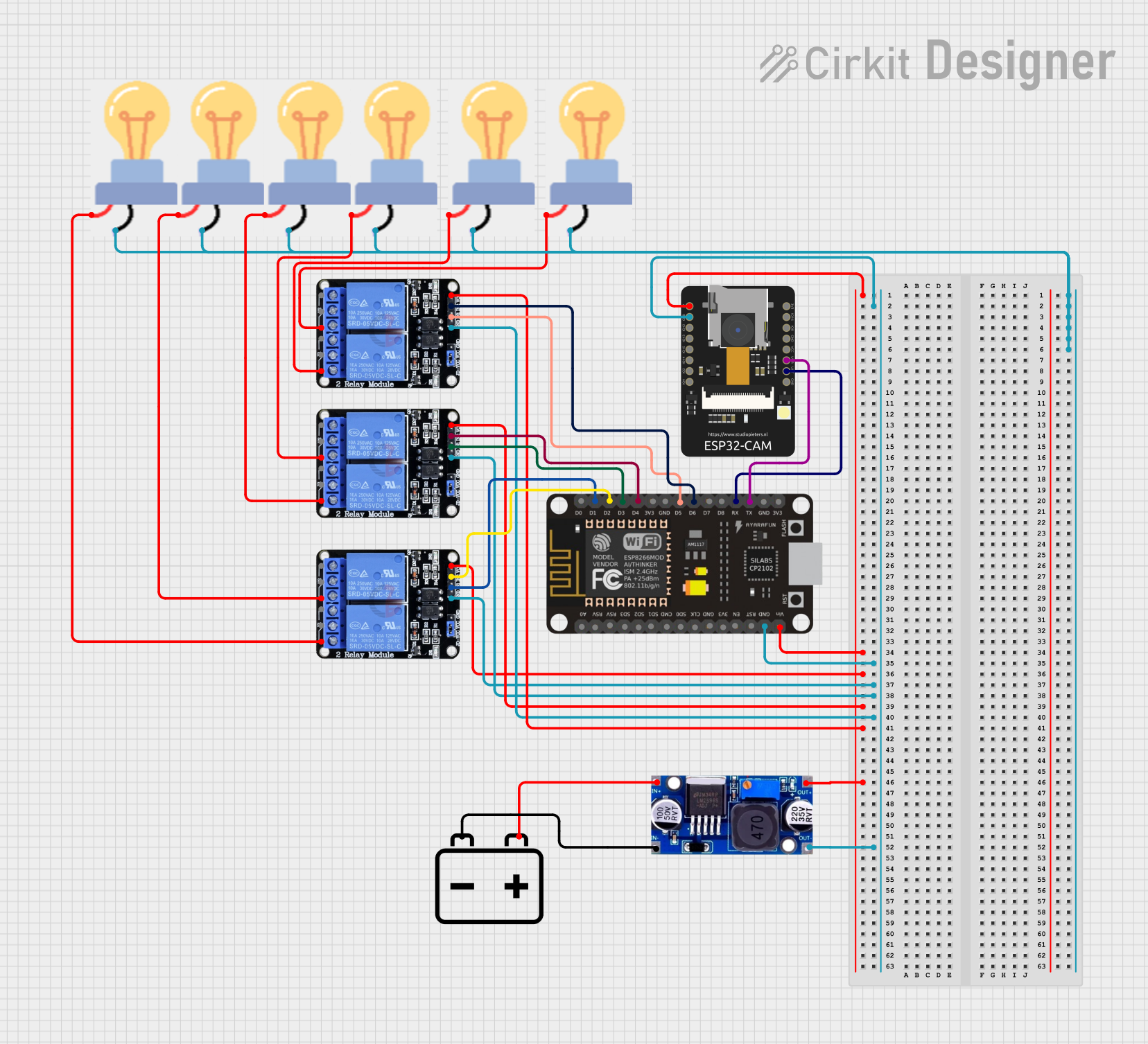
Circuit Documentation
Summary
This circuit involves an ESP8266 NodeMCU, an ESP32-CAM, three Two Channel Relay modules, several bulbs, an LM2596 voltage regulator, and a 12V battery. The ESP8266 NodeMCU controls the relays, which in turn control the bulbs. The ESP32-CAM is used for video streaming. The LM2596 voltage regulator steps down the voltage from the 12V battery to power the components.
Component List
ESP8266 NodeMCU
- Description: A low-cost Wi-Fi microcontroller with GPIO, PWM, ADC, I2C, and 1-Wire resources.
- Pins: D0, D1, D2, D3, D4, 3V3, GND, D5, D6, D7, D8, RX, TX, A0, RSV, SD3, SD2, SD1, CMD, SD0, CLK, EN, RST, VIN
ESP32-CAM
- Description: A small-sized camera module with an ESP32-S chip, capable of video streaming.
- Pins: 5V, GND, IO12, IO13, IO15, IO14, IO2, IO4, VOT, VOR, VCC, IO0, IO16, 3V3
Two Channel Relay 5V (3 instances)
- Description: A relay module that allows control of high voltage devices like bulbs.
- Pins: VCC, IN2, IN1, GND, NC2, C2, NO2, NC1, C1, NO1
Bulb (6 instances)
- Description: Standard light bulbs controlled by the relay modules.
- Pins: GND, power
12V Battery
- Description: A power source for the circuit.
- Pins: -, +
LM2596
- Description: A voltage regulator module that steps down the voltage from the 12V battery.
- Pins: IN, OUT
Wiring Details
ESP8266 NodeMCU
- VIN: Connected to 5V pin of ESP32-CAM, VCC pins of all Three Two Channel Relay modules, and OUT pin of LM2596.
- GND: Connected to GND pin of ESP32-CAM, GND pins of all Three Two Channel Relay modules, and OUT pin of LM2596.
- D1: Connected to IN1 pin of the first Two Channel Relay module.
- D2: Connected to IN2 pin of the first Two Channel Relay module.
- D3: Connected to IN1 pin of the second Two Channel Relay module.
- D4: Connected to IN2 pin of the second Two Channel Relay module.
- D5: Connected to IN1 pin of the third Two Channel Relay module.
- D6: Connected to IN2 pin of the third Two Channel Relay module.
- RX: Connected to VOT pin of ESP32-CAM.
- TX: Connected to VOR pin of ESP32-CAM.
ESP32-CAM
- 5V: Connected to VIN pin of ESP8266 NodeMCU, VCC pins of all Three Two Channel Relay modules, and OUT pin of LM2596.
- GND: Connected to GND pin of ESP8266 NodeMCU, GND pins of all Three Two Channel Relay modules, and OUT pin of LM2596.
- VOT: Connected to RX pin of ESP8266 NodeMCU.
- VOR: Connected to TX pin of ESP8266 NodeMCU.
Two Channel Relay 5V (First Instance)
- VCC: Connected to 5V pin of ESP32-CAM, VIN pin of ESP8266 NodeMCU, and OUT pin of LM2596.
- GND: Connected to GND pin of ESP32-CAM, GND pin of ESP8266 NodeMCU, and OUT pin of LM2596.
- IN1: Connected to D1 pin of ESP8266 NodeMCU.
- IN2: Connected to D2 pin of ESP8266 NodeMCU.
- NO1: Connected to power pin of the second bulb.
- NO2: Connected to power pin of the first bulb.
Two Channel Relay 5V (Second Instance)
- VCC: Connected to 5V pin of ESP32-CAM, VIN pin of ESP8266 NodeMCU, and OUT pin of LM2596.
- GND: Connected to GND pin of ESP32-CAM, GND pin of ESP8266 NodeMCU, and OUT pin of LM2596.
- IN1: Connected to D3 pin of ESP8266 NodeMCU.
- IN2: Connected to D4 pin of ESP8266 NodeMCU.
- NO1: Connected to power pin of the fourth bulb.
- NO2: Connected to power pin of the third bulb.
Two Channel Relay 5V (Third Instance)
- VCC: Connected to 5V pin of ESP32-CAM, VIN pin of ESP8266 NodeMCU, and OUT pin of LM2596.
- GND: Connected to GND pin of ESP32-CAM, GND pin of ESP8266 NodeMCU, and OUT pin of LM2596.
- IN1: Connected to D5 pin of ESP8266 NodeMCU.
- IN2: Connected to D6 pin of ESP8266 NodeMCU.
- NO1: Connected to power pin of the sixth bulb.
- NO2: Connected to power pin of the fifth bulb.
Bulbs
- GND: All bulbs' GND pins are interconnected.
- Power:
- First bulb: Connected to NO2 pin of the first Two Channel Relay module.
- Second bulb: Connected to NO1 pin of the first Two Channel Relay module.
- Third bulb: Connected to NO2 pin of the second Two Channel Relay module.
- Fourth bulb: Connected to NO1 pin of the second Two Channel Relay module.
- Fifth bulb: Connected to NO2 pin of the third Two Channel Relay module.
- Sixth bulb: Connected to NO1 pin of the third Two Channel Relay module.
12V Battery
- -: Connected to IN pin of LM2596.
- +: Connected to IN pin of LM2596.
LM2596
- IN: Connected to + and - pins of the 12V battery.
- OUT: Connected to 5V pin of ESP32-CAM, VIN pin of ESP8266 NodeMCU, and VCC pins of all Three Two Channel Relay modules. Also connected to GND pin of ESP32-CAM, GND pin of ESP8266 NodeMCU, and GND pins of all Three Two Channel Relay modules.
Code
No code provided for this circuit.