
Flame Sensor Activated Water Pump and Buzzer System with LED Indicator
View and Edit Project In Cirkit Designer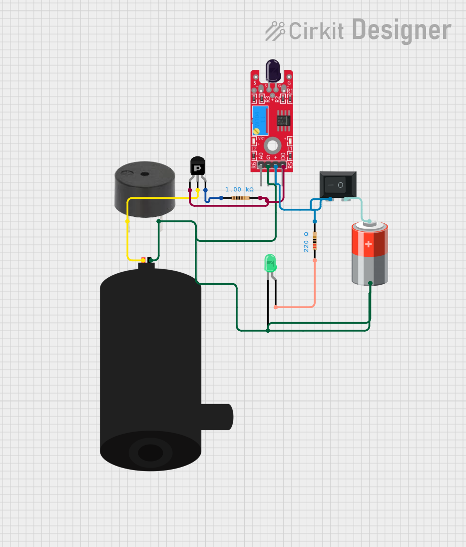
Circuit Documentation
Summary
This circuit is designed to detect flames using a KY-026 Flame Sensor and activate a water pump and buzzer in response. The circuit also includes an LED indicator and is powered by a 5V battery. A rocker switch is used to control the power supply to the circuit.
Component List
PNP Transistor (ECB)
- Pins: emitter, collector, base
- Description: A PNP transistor used to switch the water pump and buzzer.
Resistor (1k Ohms)
- Pins: pin1, pin2
- Description: A resistor with a resistance of 1000 Ohms.
Resistor (220 Ohms)
- Pins: pin1, pin2
- Description: A resistor with a resistance of 220 Ohms.
Buzzer
- Pins: PIN, GND
- Description: A buzzer that sounds an alarm when a flame is detected.
Water Pump
- Pins: positive, negative
- Description: A water pump that activates to extinguish the flame.
5V Battery
- Pins: +, -
- Description: A 5V battery that powers the circuit.
KY-026 Flame Sensor
- Pins: AO, GND, VCC, DO
- Description: A flame sensor that detects the presence of a flame.
LED: Two Pin (green)
- Pins: cathode, anode
- Description: A green LED that indicates the status of the circuit.
Rocker Switch (SPST)
- Pins: 1, 2
- Description: A single-pole single-throw (SPST) rocker switch used to control the power supply.
Wiring Details
PNP Transistor (ECB)
- Emitter: Connected to the DO pin of the KY-026 Flame Sensor and pin2 of the 1k Ohm Resistor.
- Collector: Connected to the positive pin of the water pump and the PIN of the buzzer.
- Base: Connected to pin1 of the 1k Ohm Resistor.
Resistor (1k Ohms)
- Pin1: Connected to the base of the PNP Transistor.
- Pin2: Connected to the emitter of the PNP Transistor and the DO pin of the KY-026 Flame Sensor.
Resistor (220 Ohms)
- Pin1: Connected to the anode of the LED.
- Pin2: Connected to pin2 of the Rocker Switch and the VCC pin of the KY-026 Flame Sensor.
Buzzer
- PIN: Connected to the collector of the PNP Transistor.
- GND: Connected to the negative pin of the water pump, the cathode of the LED, the - pin of the 5V Battery, and the GND pin of the KY-026 Flame Sensor.
Water Pump
- Positive: Connected to the collector of the PNP Transistor.
- Negative: Connected to the GND pin of the buzzer, the cathode of the LED, the - pin of the 5V Battery, and the GND pin of the KY-026 Flame Sensor.
5V Battery
- +: Connected to pin1 of the Rocker Switch.
- -: Connected to the negative pin of the water pump, the GND pin of the buzzer, the cathode of the LED, and the GND pin of the KY-026 Flame Sensor.
KY-026 Flame Sensor
- DO: Connected to the emitter of the PNP Transistor and pin2 of the 1k Ohm Resistor.
- GND: Connected to the negative pin of the water pump, the GND pin of the buzzer, the cathode of the LED, and the - pin of the 5V Battery.
- VCC: Connected to pin2 of the Rocker Switch and pin2 of the 220 Ohm Resistor.
LED: Two Pin (green)
- Anode: Connected to pin1 of the 220 Ohm Resistor.
- Cathode: Connected to the negative pin of the water pump, the GND pin of the buzzer, the - pin of the 5V Battery, and the GND pin of the KY-026 Flame Sensor.
Rocker Switch (SPST)
- Pin1: Connected to the + pin of the 5V Battery.
- Pin2: Connected to pin2 of the 220 Ohm Resistor and the VCC pin of the KY-026 Flame Sensor.
Code
There is no microcontroller code provided for this circuit.