
Circuit Documentation
Summary of the Circuit
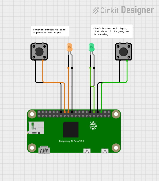
This circuit is designed around the Raspberry Pi Zero as the central processing unit, interfacing with two tactile switch buttons and two LEDs (one green and one orange). The tactile switches are used as input devices, likely for user interaction, while the LEDs serve as output indicators. The Raspberry Pi Zero's GPIO pins are utilized to interface with these components. The circuit does not include any microcontroller code, suggesting that the functionality is either not yet implemented or is managed by software running directly on the Raspberry Pi Zero.
Component List
Raspberry Pi Zero
- Description: A low-cost, compact version of the Raspberry Pi featuring a Broadcom BCM2835 SoC, with a 1GHz ARM11 core and on-board memory.
- Purpose: Acts as the central processing unit of the circuit, running the operating system and user applications, interfacing with other components via GPIO pins.
Tactile Switch Buttons - 12mm Square (x2)
- Description: Simple momentary push-button switches.
- Purpose: Serve as user input devices, allowing the user to interact with the circuit by sending signals to the Raspberry Pi Zero when pressed.
LED: Two Pin (green)
- Description: A basic green LED with two pins, anode and cathode.
- Purpose: Acts as an output indicator, which can be turned on or off by the Raspberry Pi Zero to signal various states or events.
LED: Two Pin (orange)
- Description: A basic orange LED with two pins, anode and cathode.
- Purpose: Similar to the green LED, it serves as an output indicator for different states or events.
Wiring Details
Raspberry Pi Zero
- 5V: Power supply (not connected in this circuit)
- 3.3V: Power supply (not connected in this circuit)
- GPIO2 (SDA): I2C Data (not connected in this circuit)
- GND: Connected to the common ground of the circuit
- GPIO3 (SCL): I2C Clock (not connected in this circuit)
- GPIO23: Connected to Tactile Switch Button (pin 4)
- GPIO24: Connected to LED: Two Pin (orange) (pin cathode)
- GPIO12: Connected to LED: Two Pin (green) (pin cathode)
- GPIO16: Connected to Tactile Switch Button (pin 4)
Tactile Switch Buttons - 12mm Square
- Pin 3: Connected to Raspberry Pi Zero (GND)
- Pin 4: Connected to Raspberry Pi Zero (GPIO23 for one switch, GPIO16 for the other)
LED: Two Pin (green)
- Anode: Connected to Raspberry Pi Zero (GND)
- Cathode: Connected to Raspberry Pi Zero (GPIO12)
LED: Two Pin (orange)
- Anode: Connected to Raspberry Pi Zero (GND)
- Cathode: Connected to Raspberry Pi Zero (GPIO24)
Documented Code
There is no embedded code provided for the microcontrollers in this circuit. The functionality of the circuit is likely controlled by software running on the Raspberry Pi Zero, which is not included in the provided documentation. Users should develop or obtain the appropriate software to manage the GPIO interactions with the switches and LEDs.