
Circuit Documentation
Summary
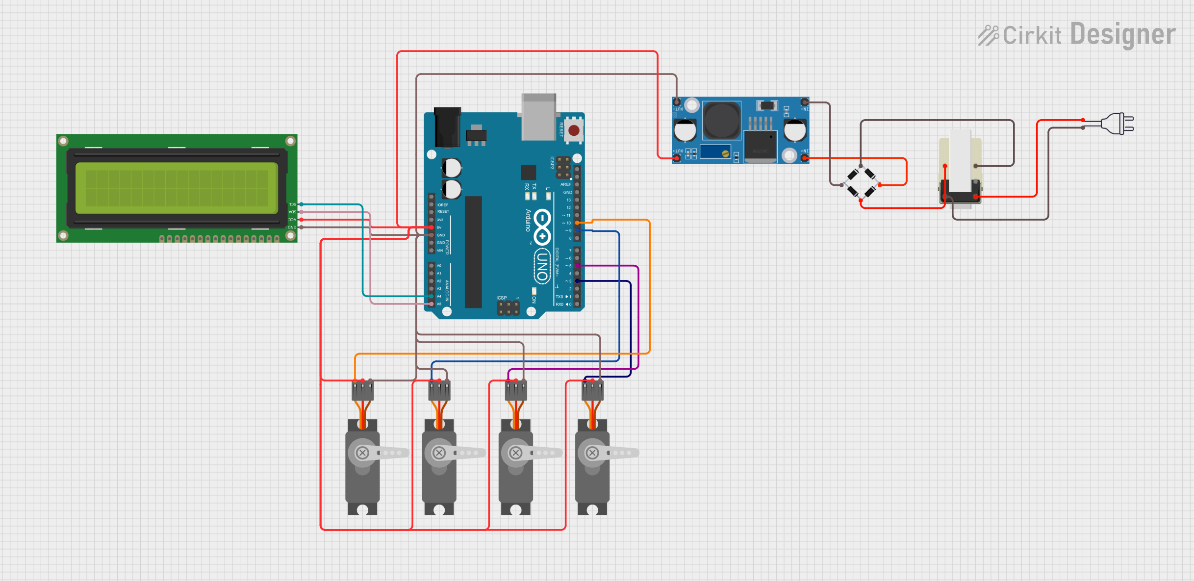
This circuit is designed to interface an Arduino UNO with multiple peripherals including a 16x2 I2C LCD and four Servo motors. The circuit is powered by a 220V AC power source, which is stepped down and rectified to DC using a Transformer and a Bridge Rectifier, respectively. The rectified voltage is then regulated to a lower DC voltage using an LM2956 Buck Converter. The Arduino UNO controls the Servo motors and communicates with the LCD over the I2C bus.
Component List
Arduino UNO
- Microcontroller board based on the ATmega328P
- It has 14 digital input/output pins, 6 analog inputs, a 16 MHz quartz crystal, a USB connection, a power jack, an ICSP header, and a reset button.
Transformer
- A device that transfers electrical energy between two or more circuits through electromagnetic induction.
Power 220V
- The main AC power source for the circuit.
Bridge Rectifier
- A circuit that converts an AC input into a DC output.
LM2956 Buck Converter DC-DC
- A DC-DC converter that steps down voltage from a higher voltage to a lower voltage.
16x2 I2C LCD
- A liquid crystal display capable of displaying 16 characters per line, with 2 lines.
- Uses I2C communication protocol.
Servo (Wokwi Compatible)
- An actuator that has the capability to be positioned to a specific angular position by sending it a PWM (Pulse Width Modulation) signal.
Wiring Details
Arduino UNO
- 5V: Connected to the V+ of all Servo motors, VCC of the 16x2 I2C LCD, and OUT+ of the LM2956 Buck Converter.
- GND: Connected to the GND of all Servo motors, GND of the 16x2 I2C LCD, and OUT- of the LM2956 Buck Converter.
- A4 (SCL): Connected to the SCL pin of the 16x2 I2C LCD.
- A5 (SDA): Connected to the SDA pin of the 16x2 I2C LCD.
- D3, D5, D9, D10: Connected to the PWM pins of the Servo motors.
Transformer
- 5, 1: Connected to the input pins of the Bridge Rectifier (Source_in-, source_in+).
- 2, 3: Connected to the 220V power source (neutral wire, hot wire).
Bridge Rectifier
- Source_in-, source_in+: Connected to the Transformer.
- Source_out-, source_out+: Connected to the input pins of the LM2956 Buck Converter (IN-, IN+).
LM2956 Buck Converter DC-DC
- IN+, IN-: Connected to the output pins of the Bridge Rectifier (source_out+, source_out-).
- OUT+, OUT-: Connected to the 5V and GND pins of the Arduino UNO, respectively.
16x2 I2C LCD
- GND: Connected to the GND of the Arduino UNO.
- VCC: Connected to the 5V of the Arduino UNO.
- SDA: Connected to the A5 pin of the Arduino UNO.
- SCL: Connected to the A4 pin of the Arduino UNO.
Servo (Wokwi Compatible)
- GND: Connected to the GND of the Arduino UNO.
- V+: Connected to the 5V of the Arduino UNO.
- PWM: Connected to the digital pins D3, D5, D9, D10 of the Arduino UNO.
Documented Code
Arduino UNO Code (sketch.ino)
void setup() {
  // put your setup code here, to run once:

}

void loop() {
  // put your main code here, to run repeatedly:

}
Note: The provided code is a template and does not include specific functionality. It needs to be completed with the setup and loop code to control the Servo motors and communicate with the LCD.