
ESP32-Based Automated Weather Station with Solar Charging and Actuator Control
View and Edit Project In Cirkit Designer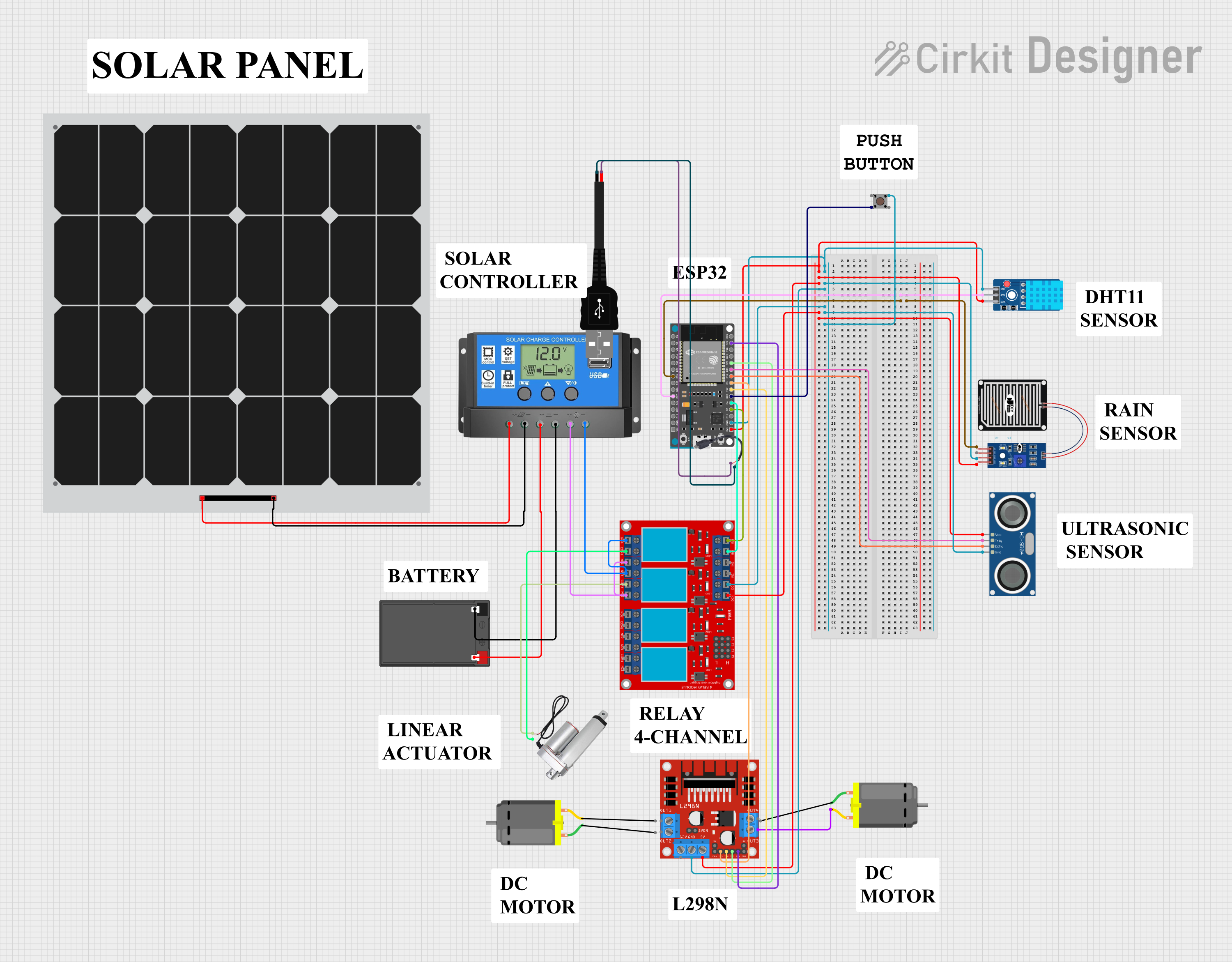
Circuit Documentation
Summary
This circuit integrates various components to perform a set of functions that likely involve environmental sensing, control, and actuation. The ESP32 Devkit V1 serves as the central processing unit, interfacing with sensors like the DHT11 for temperature and humidity readings and the RAIN SENSOR for detecting rainfall. The circuit also includes a solar power management system with a Solar Panel and Solar Charge Controller to charge a 12v 7ah Battery. Actuation is handled by a Linear actuator and DC Motors, with the L298N DC motor driver and a 4 channel relay module to control power delivery. The HC-SR04 Ultrasonic Sensor is used for distance measurement, and a Pushbutton provides user input. Power connectivity is provided through a USB male 2 pin connection and a Micro USB to Cable (2 Pin).
Component List
ESP32 Devkit V1
- Microcontroller development board with WiFi and Bluetooth capabilities.
- Pins: 3V3, GND, D15, D2, D4, RX2, TX2, D5, D18, D19, D21, RX0, TX0, D22, D23, EN, VP, VN, D34, D35, D32, D33, D25, D26, D27, D14, D12, D13, VIN
DHT11 Sensor V2
- A basic, ultra low-cost digital temperature and humidity sensor.
- Pins: GND, DAT, VCC
12v 7ah Battery
- A rechargeable battery providing a 12V power source.
- Pins: 12v +, 12v -
Solar Charge Controller
- Regulates the voltage and current coming from the solar panels going to the battery.
- Pins: Solar Cell +, Solar Cell -, Battery +, Battery -, Load +, Load -
Linear Actuator
- An actuator that creates motion in a straight line.
- Pins: +, -
Solar Panel
- Converts solar energy into electrical energy.
- Pins: +, -
RAIN SENSOR
- Detects rainwater and provides an analog output.
- Pins: AO, DO, GRD, VCC
4 Channel Relay Module
- An electrically operated switch that allows you to turn on or off a circuit using voltage and/or current much higher than a microcontroller can handle.
- Pins: N.O. 4, COM 4, N.C. 4, N.O. 3, COM 3, N.C. 3, N.O. 2, COM 2, N.C. 2, N.O. 1, COM 1, N.C. 1, Pin 13, Pin 14, Pin 15, Pin 16, Pin 17, Pin 18, Pin 19, Pin 20, Pin 21, Pin 22, Pin 23, Pin 24, VCC+, VCC- (GND), IN 1, IN 2, IN 3, IN 4
DC Motor
- Converts electrical energy into mechanical energy.
- Pins: pin 1, pin 2
USB Male 2 Pin Connection
- Provides a connection to a USB power source.
- Pins: Negative -, Positive +
Micro USB to Cable (2 Pin)
- Provides a micro USB connection to a 2 pin power source.
- Pins: Micro USB, +, -
L298N DC Motor Driver
- A high current dual full-bridge driver designed to accept standard TTL logic levels.
- Pins: OUT1, OUT2, 12V, GND, 5V, OUT3, OUT4, 5V-ENA-JMP-I, 5V-ENA-JMP-O, +5V-J1, +5V-J2, ENA, IN1, IN2, IN3, IN4, ENB
HC-SR04 Ultrasonic Sensor
- Measures distance by using ultrasonic waves.
- Pins: VCC, TRIG, ECHO, GND
Pushbutton
- A simple switch mechanism for controlling some aspect of a machine or a process.
- Pins: Pin 3 (out), Pin 4 (out), Pin 1 (in), Pin 2 (in)
Wiring Details
ESP32 Devkit V1
- 3V3: Connected to VCC of DHT11 Sensor V2, RAIN SENSOR, L298N DC motor driver, 4 channel relay module, HC-SR04 Ultrasonic Sensor
- GND: Connected to GND of DHT11 Sensor V2, RAIN SENSOR, L298N DC motor driver, 4 channel relay module, HC-SR04 Ultrasonic Sensor, Pushbutton
- D27: Connected to DAT of DHT11 Sensor V2
- D33: Connected to AO of RAIN SENSOR
- D2: Connected to IN 4 of 4 channel relay module
- D4: Connected to IN 3 of 4 channel relay module
- RX2: Connected to Pin 1 (in) of Pushbutton
- TX2: Connected to IN2 of L298N DC motor driver
- D5: Connected to IN1 of L298N DC motor driver
- D18: Connected to ECHO of HC-SR04 Ultrasonic Sensor
- D19: Connected to TRIG of HC-SR04 Ultrasonic Sensor
- D21: Connected to IN3 of L298N DC motor driver
- D22: Connected to IN4 of L298N DC motor driver
DHT11 Sensor V2
- DAT: Connected to D27 of ESP32 Devkit V1
- VCC: Connected to 3V3 of ESP32 Devkit V1
- GND: Connected to GND of ESP32 Devkit V1
RAIN SENSOR
- AO: Connected to D33 of ESP32 Devkit V1
- VCC: Connected to 3V3 of ESP32 Devkit V1
- GRD: Connected to GND of ESP32 Devkit V1
4 Channel Relay Module
- VCC+: Connected to 3V3 of ESP32 Devkit V1
- VCC- (GND): Connected to GND of ESP32 Devkit V1
- IN 4: Connected to D2 of ESP32 Devkit V1
- IN 3: Connected to D4 of ESP32 Devkit V1
- N.C. 4, N.C. 3: Connected to Load + of Solar Charge Controller
- N.O. 4, N.O. 3: Connected to Load - of Solar Charge Controller
- COM 3: Connected to + of Linear actuator
- COM 4: Connected to - of Linear actuator
L298N DC Motor Driver
- 5V: Connected to 3V3 of ESP32 Devkit V1
- GND: Connected to GND of ESP32 Devkit V1
- IN1: Connected to D5 of ESP32 Devkit V1
- IN2: Connected to TX2 of ESP32 Devkit V1
- IN3: Connected to D21 of ESP32 Devkit V1
- IN4: Connected to D22 of ESP32 Devkit V1
- OUT3: Connected to pin 2 of DC Motor
HC-SR04 Ultrasonic Sensor
- VCC: Connected to 3V3 of ESP32 Devkit V1
- TRIG: Connected to D19 of ESP32 Devkit V1
- ECHO: Connected to D18 of ESP32 Devkit V1
- GND: Connected to GND of ESP32 Devkit V1
Pushbutton
- Pin 1 (in): Connected to RX2 of ESP32 Devkit V1
- Pin 4 (out): Connected to GND of ESP32 Devkit V1
Solar Charge Controller
- Battery +: Connected to 12v + of 12v 7ah Battery
- Battery -: Connected to 12v - of 12v 7ah Battery
- Solar Cell +: Connected to + of Solar Panel
- Solar Cell -: Connected to - of Solar Panel
- Load +: Connected to N.C. 4, N.C. 3 of 4 channel relay module
- Load -: Connected to N.O. 4, N.O. 3 of 4 channel relay module
Solar Panel
- +: Connected to Solar Cell + of Solar Charge Controller
- -: Connected to Solar Cell - of Solar Charge Controller
Linear Actuator
- +: Connected to COM 3 of 4 channel relay module
- -: Connected to COM 4 of 4 channel relay module
DC Motor
- pin 2: Connected to OUT3 of L298N DC motor driver
USB Male 2 Pin Connection
- Negative -: Connected to - of Micro USB to Cable (2 Pin)
- Positive +: Connected to + of Micro USB to Cable (2 Pin)
Micro USB to Cable (2 Pin)
- -: Connected to Negative - of USB Male 2 Pin Connection
- +: Connected to Positive + of USB Male 2 Pin Connection
Documented Code
No code has been provided for the microcontrollers in the circuit. If code is later provided, it should be documented here with explanations of how it interacts with the connected components and implements the circuit's functionality.